
Multi-frequency transmitter using predistortion and a method of transmitting

A transmitter, pre-distortion technology, applied in the direction of look-up table adaptive pre-distortion, improved amplifier to reduce nonlinear distortion, multi-carrier system, etc.

Inactive Publication Date: 2002-02-20
NOKIA NETWORKS OY
View PDF1 Cites 9 Cited by
  • Summary
  • Abstract
  • Description
  • Claims
  • Application Information

AI Technical Summary

Problems solved by technology

[0010] It is an object of embodiments of the present invention to provide a transmitter that can have only one transmission path and that solves or at least alleviates the problems caused by non-linear amplifiers

Method used


Image

  • Multi-frequency transmitter using predistortion and a method of transmitting
  • Multi-frequency transmitter using predistortion and a method of transmitting
  • Multi-frequency transmitter using predistortion and a method of transmitting

Examples


no. 2 example

[0063] now refer to Figure 6 , Figure 6 A third embodiment of the invention is shown. As with the second embodiment of the invention, only the differences between the first and third embodiments will be discussed.

[0064] Figure 4 The channelizer 140 has changed from Figure 6 omitted in the examples. The output of the analog-to-digital converter 138 is thus directly input to the input of the predistorter 108 . Since only the information in the composite signal is available, the predistorter is arranged to generate a reference.

[0065] now refer to Figure 9 , Figure 9 shows a third embodiment of a predistorter that can be used for Figure 6 in the embodiment. The third distorter 108c receives the output from the digital modulator 106 . Each output of digital modulator 106 is input to combiner 212 , which combines the outputs of modulators 212 to provide a signal that is input to subtractor 214 . A single subtractor 214 also receives the output of the analog-t...


PUM


Abstract

A multi-frequency carrier transmitter comprises input means for receiving a plurality of different digital signals to be transmitted. The different signals are to be transmitted on different carrier frequencies. Amplifier means receive a composite signal comprising the different signals at the respective carrier frequencies and amplify the composite signal. Predistortion means predistort the plurality of digital signals prior to amplification of the composite signal by the amplification means. The predistortion provided by the predistortion means is subsequently altered in dependence on the difference between the input signals and the output at the amplifier means.

Description

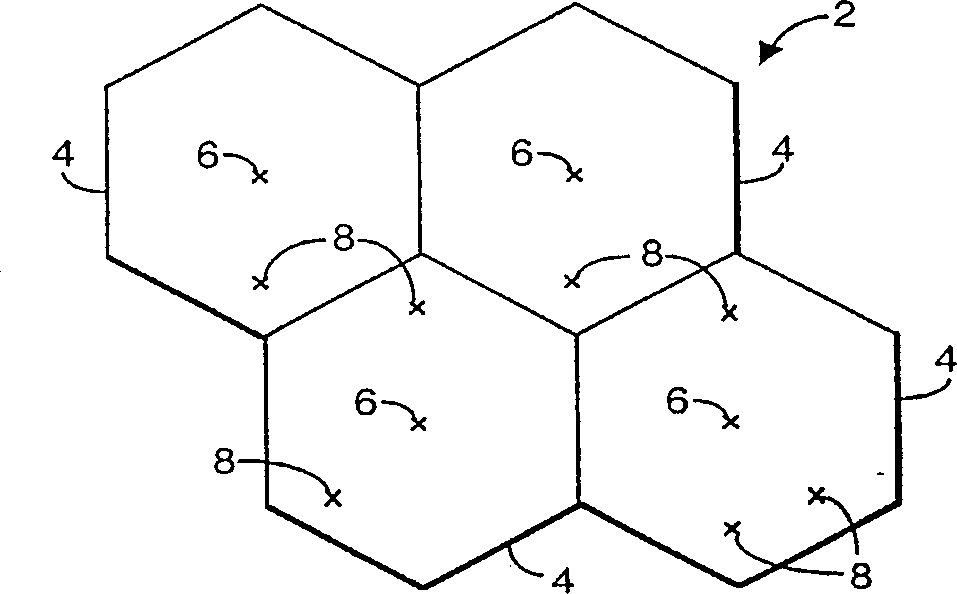
technical field [0001] The present invention relates to a transmitter and a transmitting method, especially but not exclusively to a transmitter and a transmitting method for a telecommunication network. Background technique [0002] in such as figure 1 In the shown known wireless telecommunication network 2 , the area covered by the network 2 is divided into a number of cells 4 . Each cell is connected to a base transceiver station 6 . Each base station 6 is arranged to communicate with terminals located in a cell to which the base station 6 is connected. Terminal 8 may be a mobile terminal moving between cells 4 . [0003] Each base station 6 in GSM (Global System for Mobile Communications) is set to transmit N frequencies from M available frequencies C1...CM frequencies, such as Figure 2a shown. Each of the M frequencies is different and within the bandwidth allocated to the signal transmitted by the base station. Each channel is divided into a number of sequential...

Claims


Application Information

Patent Timeline
Patent Type & Authority Applications(China)
IPC IPC(8): H04J1/02H03F1/32H04B1/04H04B1/62H04L27/36
CPCH03F1/3282H03F1/3247H04L27/368H04B1/62H03F2201/3233H03F2201/3206H04B1/04
Inventor 哈里·伯斯蒂
Owner NOKIA NETWORKS OY
Learn More