
Resin molded prism and its mold

A prism and resin technology, applied in the field of resin-molded prisms, can solve the problems of changing the shape of the optical surface and reducing the optical properties of the optical element.

Inactive Publication Date: 2002-03-13
CANON KK
View PDF2 Cites 3 Cited by
  • Summary
  • Abstract
  • Description
  • Claims
  • Application Information

AI Technical Summary

Problems solved by technology

Residual stress caused in this way not only causes birefringence, which degrades the optical characteristics of the optical element, but also causes changes in the shape of the optical surface due to stress relaxation when the optical element is used for a long time

Method used


Image

  • Resin molded prism and its mold
  • Resin molded prism and its mold
  • Resin molded prism and its mold

Examples


Embodiment Construction

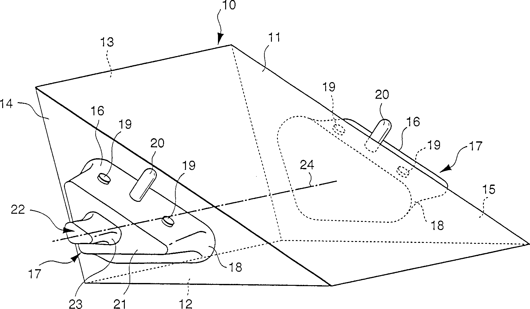
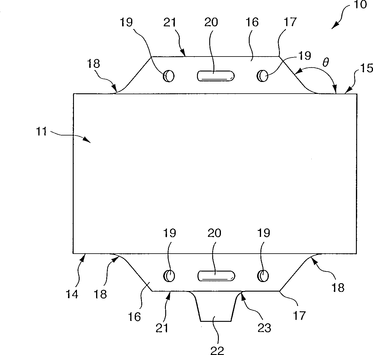
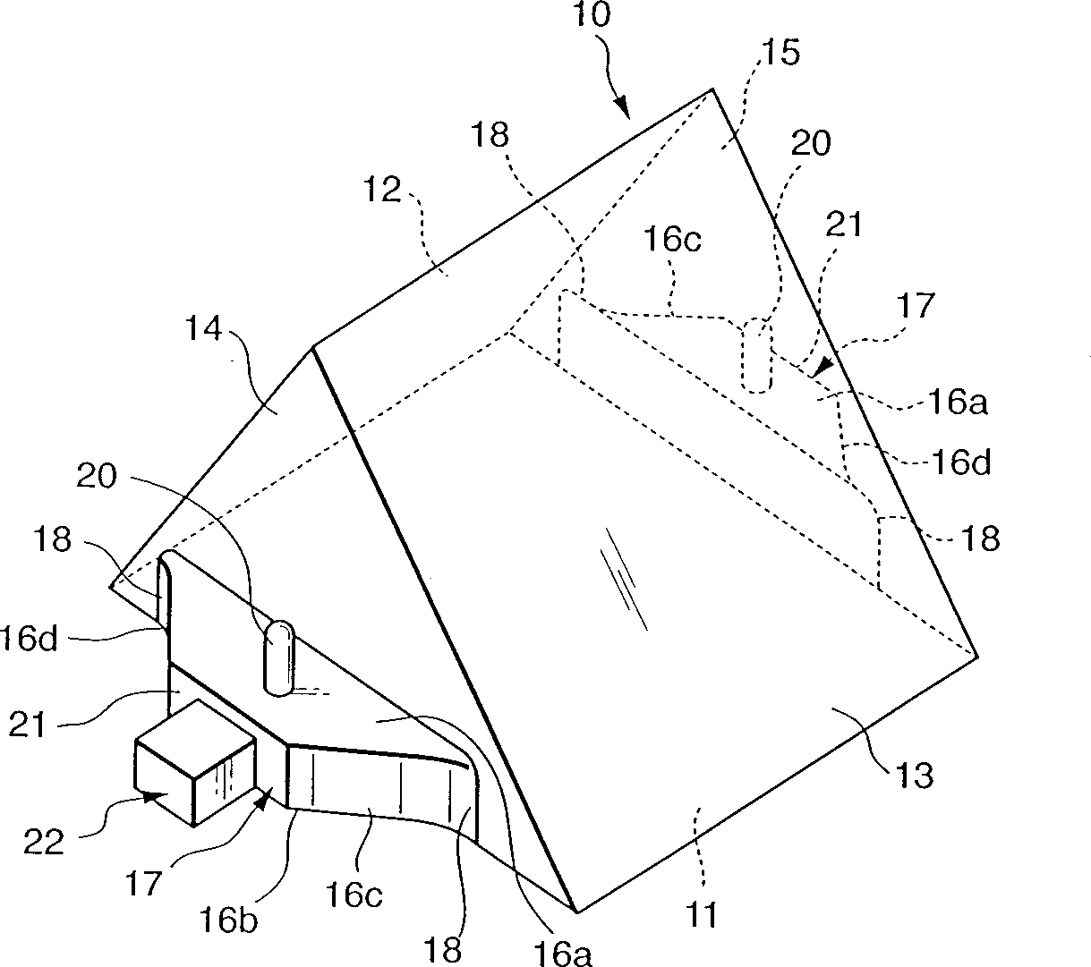
[0020] In the resin molded prism according to the first embodiment of the present invention, the positioning portion may have a plane portion parallel to an optical surface serving as a reference, and a pair of positioning pins perpendicular to each other. Protrude from the flat part. In this case, the circumferential end faces of the pair of standard blocks may each include a planar portion of the positioning portion, or the planar portion of the positioning portion may be made of at least three protruding pieces from the standard block Protrude from the circumferential end face of each of them. If the positioning portion protrudes from the peripheral end face of each of the standard block pairs in this way, when the resin flows into the cavity forming the standard block, there is no protrusion in the cavity that interferes with this flow, so The resin flows smoothly, thereby suppressing the formation of flow marks.

[0021] Preferably, the curved surface has a radius of cu...


PUM

PropertyMeasurementUnit
Radius of curvatureaaaaaaaaaa

Abstract

A flow mark or residual stress occurring in the vicinity of a gate adversely affects the optical characteristics of a resin prism which is to be formed by injection molding. Thus, the molding conditions for the resin prism are strict, and accordingly the resin prism has poor moldability. In view of this, according to this invention, the resin prism includes two or more optical surfaces (11-13) that are not parallel to each other, a pair of side end faces (14, 15) substantially perpendicular to the optical surfaces (11-13), at least one reference block (17) projecting from either one of the pair of side end faces (14, 15) and having a circumferential end face (16) extending in a projecting direction of the reference block, a positioning portion (19, 20) formed on the circumferential end face (16) of the reference block (17), and a curved surface (18) for smoothly connecting the circumferential end face (16) of the reference block (17) and corresponding one of the pair of side end faces (14, 15), wherein the circumferential end face (16) and the corresponding one of the side end faces (14, 15) form an angle of 90 DEG or more.

Description

technical field [0001] The present invention relates to a resin molded prism having excellent optical properties and manufactured by injection molding capable of high precision positioning, and a mold for injection molding the resin molded prism. Background technique [0002] A method of manufacturing an optical element from a resin according to the injection molding method has been developed for the purpose of reducing the cost and weight of the optical element. When the optical element is manufactured by injection molding, some parts for fixing and positioning relative to the optical device can be integrally molded with the optical element, so that the optical element can be easily assembled and positioned, and many components can be reduced. For example, Japanese Patent No. 2778651 discloses a device in which a positioning portion for positioning an optical prism to be manufactured by injection molding is integrally formed with the optical prism. [0003] When injecting ...

Claims


Application Information

Patent Timeline
IPC IPC(8): B29C45/00B29C45/26B29C45/76G02B5/04G02B7/18
CPCB29C45/0025B29C2045/0027B29C2045/0029G02B5/04B29L2011/00B29C45/2708
Inventor 富永隆宽
Owner CANON KK
Learn More