Lightning protector for low voltage electric equipment

A lightning protection device, low-voltage electrical technology, applied in circuit devices, emergency protection circuit devices, electrical components, etc., can solve the problems of imperfect lightning protection devices, combustion, fire, etc., to achieve easy maintenance in time, simple structure configuration, protection high-capacity effect

Inactive Publication Date: 2002-03-13
EMERSON NETWORK POWER CO LTD
View PDF1 Cites 17 Cited by
  • Summary
  • Abstract
  • Description
  • Claims
  • Application Information

AI Technical Summary

Problems solved by technology

When the former lightning protection device is in use, due to the influence of grounding resistance, when the lightning protection component is damaged, although there is a fuse connected in series in front of it, the fuse is not easy to blow, so the lightning protection component will explode or burn
When the latter lightning protection device works, it will also cause a fire because there is no fuse with an appropriate current capacity connected in series in front of the lightning protection element between the neutral line and the ground.
Chinese patent ZL98217538.8 (notification number CN2376112Y) discloses a kind of lightning protection device for above-mentioned problem, and it is mainly to be connected with overcurrent protector namely fuse before each piezoresistor of lightning protection components and gas discharge tube, and set There is an on-off indication circuit of the overcurrent protector, that is, the lightning protection alarm indication circuit, but the lightning protection device of this structure has imperfections. For the three-phase power supply system, due to the different phases of the three phases, after the neutral line fuse is blown, the The current can form a loop between the phase wires through the diode, causing the indicator light to not go out, making it difficult for the user or maintenance personnel to know the operating status of the lightning protection device, and providing wrong information to the maintenance personnel, thinking that the lightning protection device is operating normally. But in fact, the lightning protection device has lost the protection function of the common-mode lightning strike to the ground, so that the equipment is in a dangerous situation of being struck by lightning, and it is difficult to ensure the safe operation of the communication equipment.

Method used


Image

  • Lightning protector for low voltage electric equipment
  • Lightning protector for low voltage electric equipment
  • Lightning protector for low voltage electric equipment

Examples


Embodiment 1

[0027] like Figure 1-Figure 5 As shown, this embodiment includes

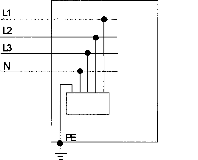
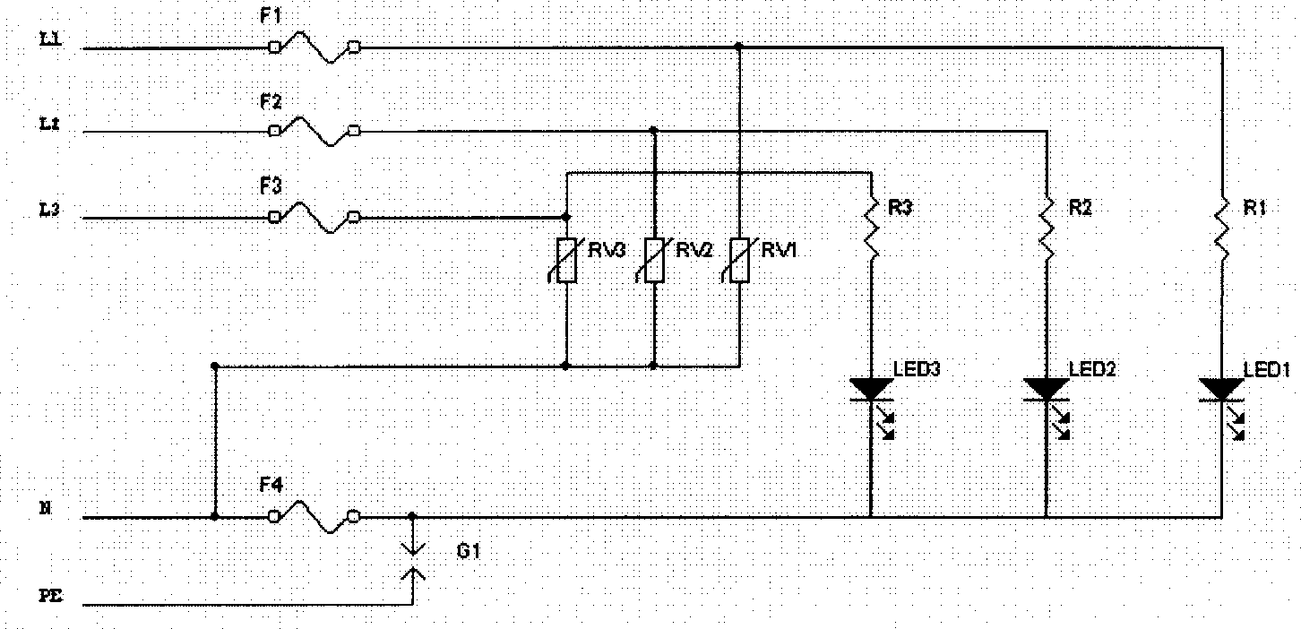
[0028] A common mode lightning protection circuit consists of three piezoresistors RV1, RV2, RV3 respectively connected between the three phase lines L1, L2, L3 and the neutral line N and one connected between the neutral line N and The gas discharge tube G1 between the ground wire PE is used to improve the protection level of the device;

[0029] An overcurrent protection device consists of three overcurrent protectors F1, F2, F3 connected in series on the phase lines L1, L2, L3 in front of the varistors RV1, RV2, RV3 respectively and a gas discharge tube G1 connected in series The overcurrent protector F4 on the front neutral line N, wherein the overcurrent protectors F1, F2, F3, and F4 all use fuses to prevent lightning protection components such as piezoresistors and gas discharge tubes from appearing Phenomenon of explosion or combustion;

[0030] A lightning protection warning indicating device, which...

Embodiment 2

[0034] like Figure 6 As shown, the difference between this embodiment and Embodiment 1 is that a varistor RV7 is connected in series between the overcurrent protector F4 on the neutral line N and the gas discharge tube G1, and the varistors RV1, RV2 The short contacts of RV3 and varistor RV7 are connected to the connection point of the gas discharge tube G1, and the short contacts of the three sets of lightning protection and alarm indication circuits are connected to the connection points of the varistor RV7 and the overcurrent protector F4. That is to say, in this embodiment, the varistor RV7 is connected in series with the discharge tube G1 between the neutral line N and the ground line PE to act as a current limiting resistor, because some remote rural power grids are unstable, and the neutral line N The potential may shift to a higher value, which will have a certain impact on the arc extinguishing of the gas discharge tube G1. Connecting the varistor RV7 in series can n...

Embodiment 3

[0036] like Figure 7-Figure 8 As shown, the difference between this embodiment and Embodiment 1 and Embodiment 2 is that the present invention also includes a differential-mode lightning protection circuit, and the differential-mode lightning protection circuit consists of three phase lines L1, L2, and L3 respectively. The varistors RV4, RV5, and RV6 between the two phase lines are composed of the varistor RV4 connected between the phase lines L1 and L2, the varistor RV5 connected between the phase lines L2 and L3, and the varistor RV6 is connected across phase lines L1 and L3. The main difference between this embodiment and the functions of Embodiment 1 and Embodiment 2 is that in Embodiment 1 and Embodiment 2, the combination of varistors RV1, RV2, and RV3 is mainly used to protect the connection between the phase lines L1, L2, and L3. Differential mode lightning strikes, that is, the differential mode lightning strikes between L1 and L2 are protected by RV1+RV2, the diffe...


PUM


Abstract

The lightning protector incldues: one common-mode lightning preventing circuit, one overcurrent protector, and one lightning preventing warning device comprising three lightning preventing warning and indicating circuits in the same structure. It features that the lightning preventing warning and indicating circuit consists of one limiting resistor and one serially connected one-way conducted lightning and indicating circuit. In the lightning preventing warning and indicating circuit, current flows in only one direction and the indicating lamp of the circuit goes out along with the blow of the overcurrent protector to indicate reliably the on-off state, and this is favorable to maintenance. The structure and configuration is simple, flexible and practical.

Description

technical field [0001] The invention relates to a lightning protection device, in particular to a lightning protection device for low-voltage electrical equipment. Background technique [0002] In order to provide lightning protection for low-voltage electrical equipment, the most effective method at present is to install lightning protection devices on the AC power supply lines of the equipment. There are two main working principles of existing lightning protection devices: one is to install lightning protection components directly to the ground on the neutral line and three phase lines respectively; the other is to install lightning protection components between the zero line and the ground, Arresters are directly installed on the three phase lines and the neutral line respectively. When the former lightning protection device is in use, due to the influence of grounding resistance, when the lightning protection component is damaged, although there is a fuse connected in s...

Claims


Application Information

Patent Timeline
Patent Type & Authority Applications(China)
IPC IPC(8): H02H3/22H02H9/04H02H9/06
Inventor 孟奇
Owner EMERSON NETWORK POWER CO LTD
Why Eureka
Try Eureka