Liquid crystal cell gap adjusting device, pressure packaged device and manufacture method for liquid crystal display

A gap adjustment device and liquid crystal cell technology, applied in static indicators, nonlinear optics, optics, etc., can solve problems such as time extension, liquid crystal device can not obtain display characteristics, plate-shaped member 90 uneven thickness, etc.

Inactive Publication Date: 2002-04-03
SEIKO EPSON CORP
View PDF0 Cites 11 Cited by
  • Summary
  • Abstract
  • Description
  • Claims
  • Application Information

AI Technical Summary

Problems solved by technology

[0007] However, in Figure 14 In the shown pressurizing device, since the plate-shaped member 90 directly contacts the substrate surface of the liquid crystal cell 1, so in order to accurately adjust the gap of the liquid crystal cell 1, the contact surface must be completely flat, but the plate-shaped member 90 There is a limit to the fact that the surface becomes such a perfect plane, and in the present case, it is inevitable that some degree of unevenness will be formed on the surface, or the thickness of the plate-like member 90 will be uneven.
Moreover, there is a problem that the liquid crystal cell gap cannot be accurately adjusted to the target value by directly processing the liquid crystal cell 1 with such an incomplete plane, and the expected display characteristics cannot be obtained in the completed liquid crystal device.
[0008] In addition, in Figure 14 In the shown pressurizing device, since the spacer paper 91 directly contacts the substrate surface of the liquid crystal cell 1, it is different from the Figure 12 The same is true for the pressure device shown, but uniform pressure cannot be applied to the substrate surface of the liquid crystal device 1, and there is a problem that desired display characteristics cannot be obtained in the completed liquid crystal device.
[0009] In addition, since the pressure applied to the plate member 90 is absorbed by the spacer paper 90 during the period from when the plate member 90 is pressurized until the spacer paper 90 is sufficiently shrunk, a desired pressure cannot be applied to the liquid crystal cell 1. on the substrate surface
As a result, there is a problem that the time for the cell gap of the liquid crystal cell 1 to reach the target value is extended by the time corresponding to the above-mentioned period.
In addition, in the case of improving production efficiency and increasing the number of processed liquid crystal cells 1, since the number of spacers 91 inserted between each liquid crystal cell increases, such a problem is particularly significant.

Method used


Image

  • Liquid crystal cell gap adjusting device, pressure packaged device and manufacture method for liquid crystal display
  • Liquid crystal cell gap adjusting device, pressure packaged device and manufacture method for liquid crystal display
  • Liquid crystal cell gap adjusting device, pressure packaged device and manufacture method for liquid crystal display

Examples


Deformed example 1

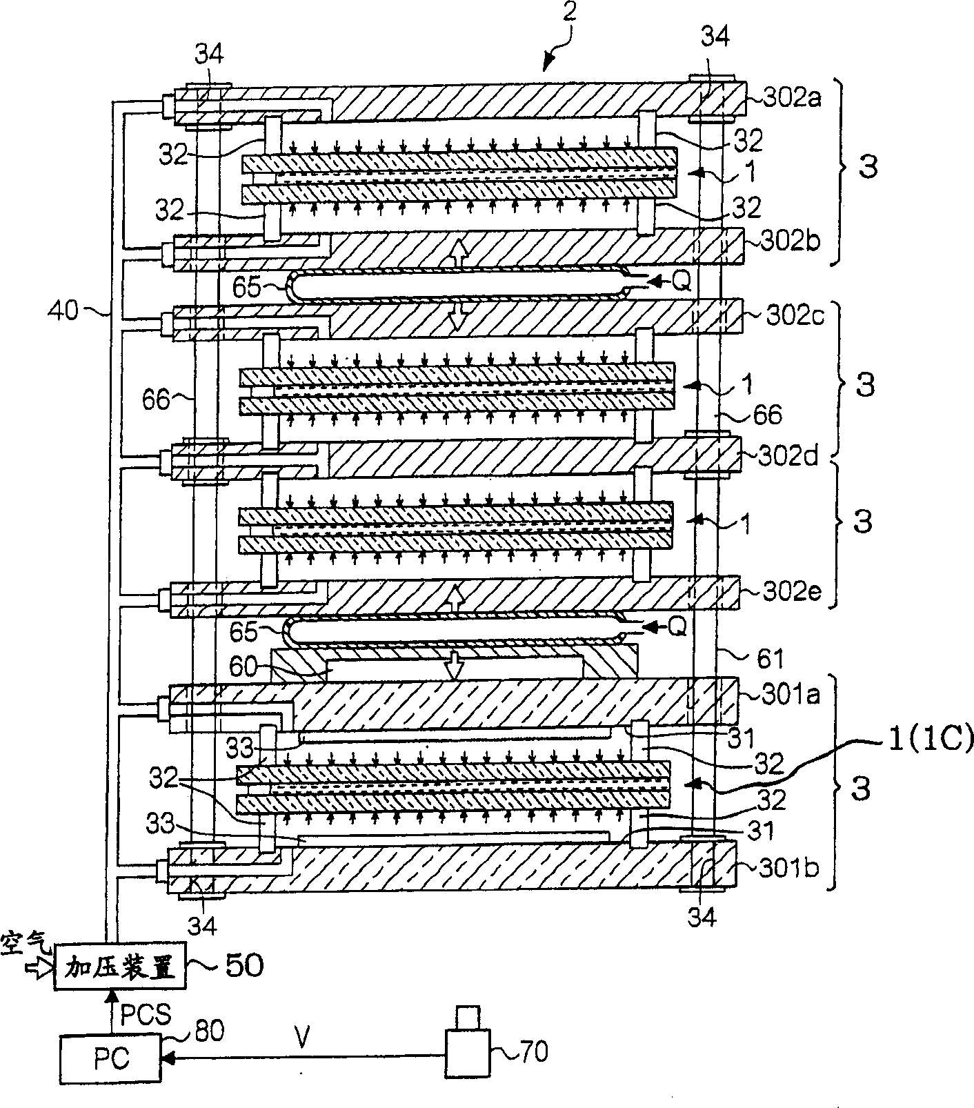
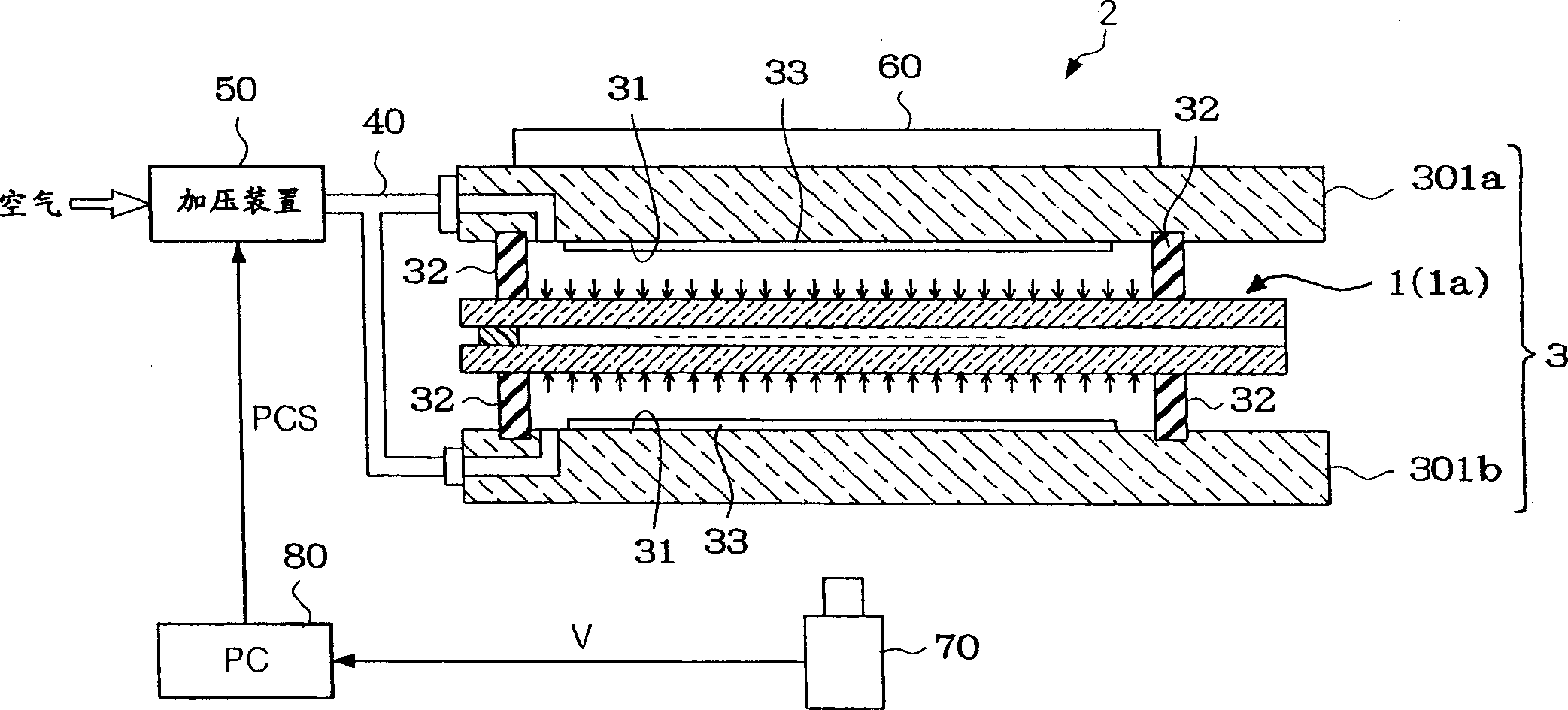
[0092] In the above-mentioned embodiment, such as figure 2 As shown, the light intensity of each monochromatic light emitted from the light source 60 and transmitted through the detection liquid crystal cell 1C is detected by the color CDD camera 70, and the liquid crystal cell gap (d) is obtained from the detection result. Here, with respect to the liquid crystal cell 1C for detection without a color filter, the liquid crystal cell gap (d) can be accurately obtained by such a method. However, when the liquid crystal cell gap (d) of the liquid crystal cell 1C for detection with a color filter is obtained by this method, since the light received by the color CDD camera 70 is light that can pass through the color filter , so the chromaticity coordinates on the CIE chromaticity diagram change with the characteristics of the color filter, which leads to the problem that the gap (d) of the liquid crystal cell may not be accurately obtained. In order to avoid such a problem, when ...

Deformed example 2

[0102] In the above-mentioned embodiment, it is assumed that the substrate surface of the liquid crystal cell group 1 and the sealing member 32 for sealing have a Image 6 In the case of the positional relationship shown above, the positional relationship is not limited to this, and the following relationship may be used.

[0103] Figure 9 (a) shows that in this modified example, the liquid crystal cell group 1 and the seal for sealing when the liquid crystal cell group 1 is supported in the liquid crystal cell gap adjusting device 2 are viewed from a direction perpendicular to the substrate surface of the liquid crystal cell group 1. A plan view of the positional relationship of piece 32. in addition, Figure 9 (b) is Figure 9 Enlarged view of region C surrounded by dashed lines in (a). like Figure 9 As shown, in this modified example, at least a part of the sealing member 32 overlaps each sealing material 13 of the liquid crystal cell group 1 when viewed from a direc...

Deformed example 3

[0110] In the above-mentioned embodiment and each modified example, although the case where the sealing member has a shape that surrounds most of the substrate area of ​​the liquid crystal cell group is given, in the case of adopting a shape that surrounds a part of the substrate area of ​​the liquid crystal cell group In the case of the sealing member, a general-purpose sealing member (that is, a general-purpose liquid crystal cell gap adjustment device) can be used to process various groups of liquid crystal cells having different substrate sizes. In addition, in the following specific description about the above, in the case of processing various types of liquid crystal cell groups 1 having different sizes of substrates, the liquid crystal cell group 1 with the largest substrate area is referred to as "liquid crystal cell group 1". 1A", and the liquid crystal cell group 1 with the smallest substrate area is referred to as "liquid crystal cell group 1B".

[0111] like Figu...


PUM


Abstract

A sell gap adjusting device with which cell gaps of one or more liquid crystal cells can be exactly and promptly adjusted, a pressure- sealing device, and to provide a manufacturing method of a liquid crystal display device. The cell gap adjusting device 2 for adjusting the thickness (cell gap) between a pair of substrates, in the liquid crystal cell 1, where a liquid crystal is injected between the pair of substrates is characteristically provided with a supporting means 3 having one or more pairs of support jigs 30 for sandwiching and supporting respective liquid crystal cells and frame shaped seals 32, for sealing which are disposed between the liquid crystal cell and the supporting jigs and whose inner surfaces form closed spaces, together with both outer surfaces of the pair of substrates of the liquid crystal cell and surfaces opposed to the liquid crystal cell 1 of the pair of support jigs and a pressurizing means 50, for simultaneously pressurizing both the outer surfaces of the pairs of substrates of the liquid crystal cell 1 by the pressure of the fluid introduced into the hermetically sealed space.

Description

technical field [0001] The present invention relates to a liquid crystal cell gap adjusting device for adjusting a gap between a pair of substrates in a liquid crystal cell (hereinafter referred to as "liquid crystal cell gap"), a pressure sealing device and a method for manufacturing a liquid crystal display device. Background technique [0002] The liquid crystal device widely used so far is generally manufactured in this way, that is, a pair of opposing substrates are bonded to form a liquid crystal cell through a sealing material having a frame shape and an opening at a predetermined position on the frame wall, and then the liquid crystal cell is formed by The above-mentioned opening of the sealing material is manufactured by injecting liquid crystal into the liquid crystal cell and sealing the opening with the sealing material. Here, a so-called vacuum injection method is widely used as a method of injecting liquid crystal into the above-mentioned liquid crystal cell. ...

Claims


Application Information

Patent Timeline
Patent Type & Authority Applications(China)
IPC IPC(8): G02F1/13G02F1/1333G02F1/13357G02F1/1339G02F1/1341
CPCG02F1/1333G02F1/1341G02F1/1339
Inventor 增田健治黑岩雅宏
Owner SEIKO EPSON CORP
Why Eureka
Try Eureka