
Cleanable helical modules

a technology of helical modules and helical parts, applied in the field of cleanable helical modules, can solve the problems of affecting the safety of products, affecting the quality of products, so as to achieve the effect of simple separation of components, easy assembly, and easy re-assembling of helical parts

Inactive Publication Date: 2011-11-29
BAYER INTELLECTUAL PROPERTY GMBH
View PDF20 Cites 5 Cited by
  • Summary
  • Abstract
  • Description
  • Claims
  • Application Information

AI Technical Summary

Benefits of technology

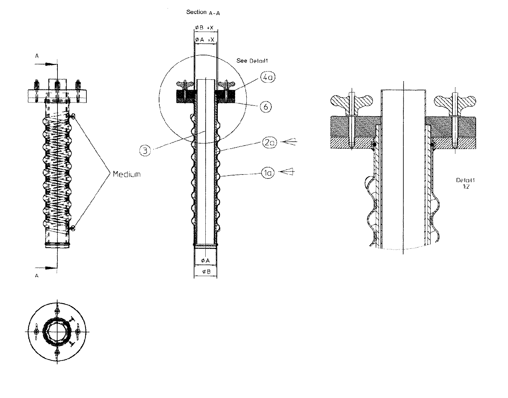
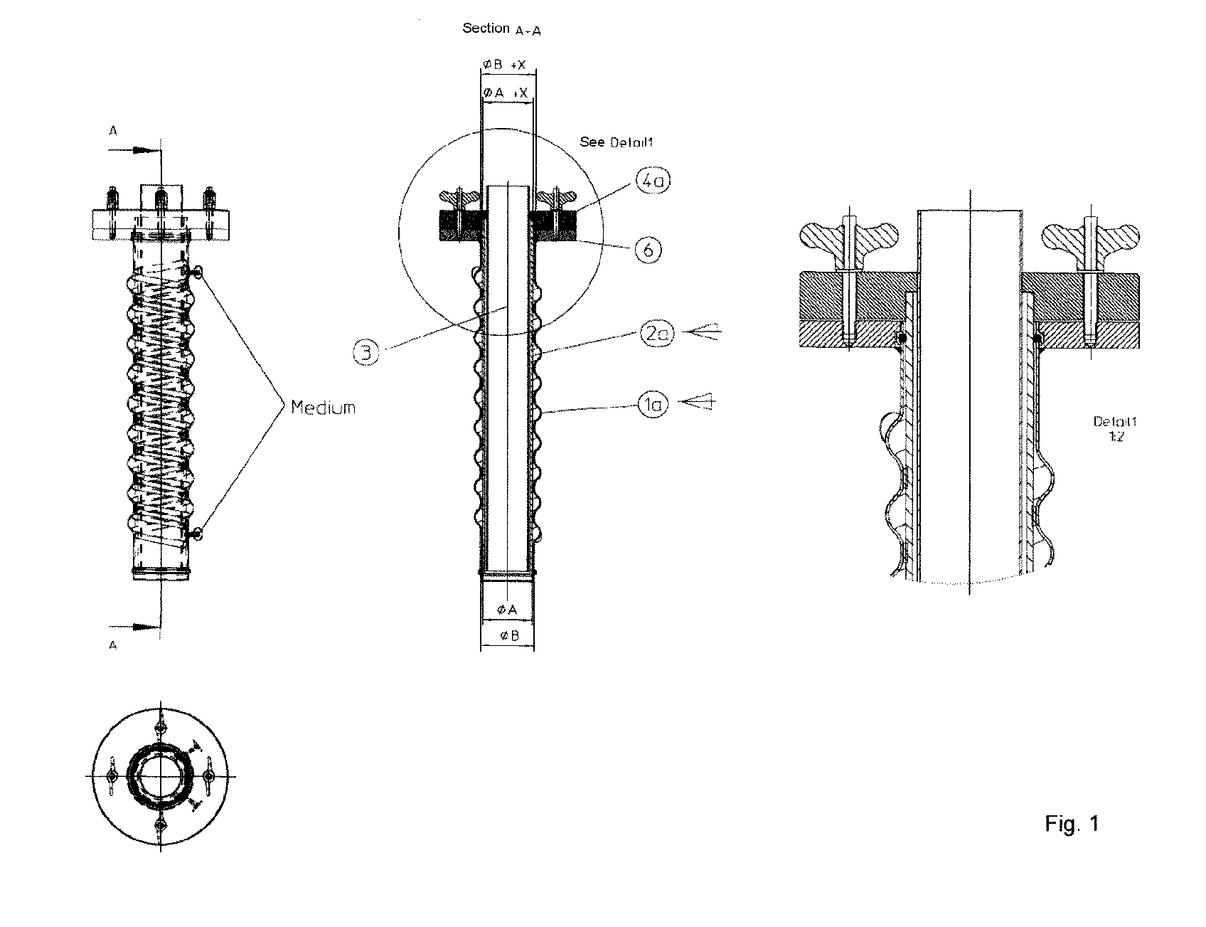
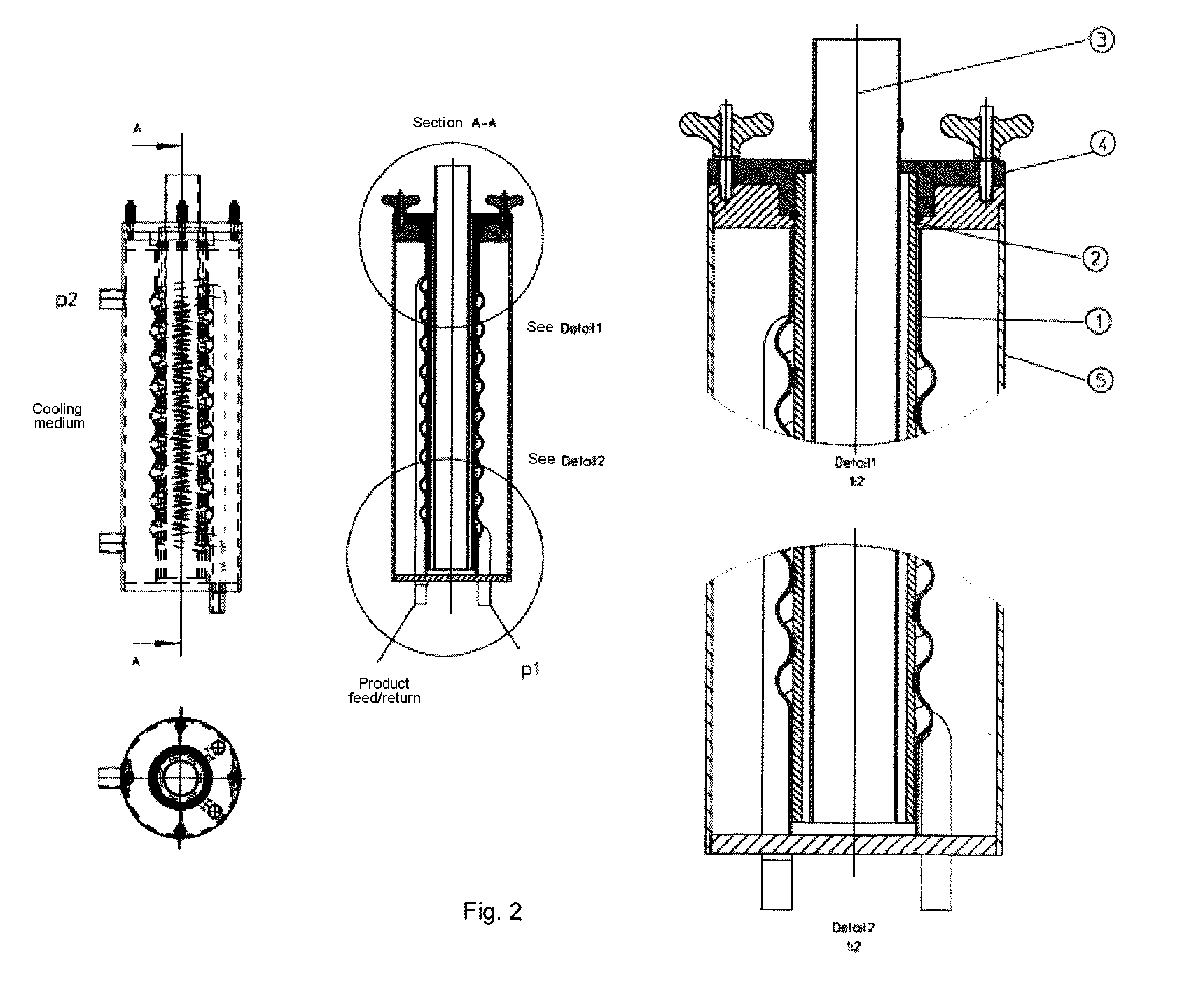
[0016]In one embodiment, the module according to the invention is characterized in that it makes possible a relative movement of the individual components, in particular of the tube (2 or 2a) and the helix (1 or 1a), preferably by way of an internal rotor 8c which is connected to the cover tube (2 or 2a) and thus mechanical in-situ cleaning is carried out. The touching helical face of the helix can here be provided with a seal. This also enables material combinations which would otherwise not permit a form-fitting connection, such as a combination of quartz glass tube and metal helix. It is also possible to use tubes made of plastics which are transparent or partially transparent to radiation rather than the quartz glass tube. The inventive embodiment of the seal can prevent the surface from being scratched during a relative movement. Such scratching would destroy the important optical properties. The processed fluid itself can here also serve as lubricant without the irradiation being prevented thereby. A thin film ensuring sufficient irradiation forms in this case between quartz glass and seal. Ablated impurities and deposits are removed from the module by way of the rotating helical seal. The relative mobility due to the lubricated seal also enables a pulling off of the helix from the tube and separate cleaning of both components.
[0027]An additional possibility of cleaning is the physical introduction of a pig or of a helical insert which is pushed through the channel. This can be done mechanically, using compressed air or a fluid. On account of running through the helical channel, a mechanical cleaning effect ensues. This can also be enhanced by moving tube and helix with respect to each other when the insert is introduced and thus producing an additional relative movement also with respect to the insert.

Problems solved by technology

Contamination with active, i.e. capable of reproduction, biological materials such as microorganisms or viruses often poses a risk to product safety which has to be countered effectively.
It is a considerable technical challenge if, besides the germs to be inactivated, materials of value are also present which, to a certain degree, can also be damaged by the radiation.
Additional difficulties arise when the clouding of the processed liquid in the range of the UV-C radiation is high and thus the penetration depth of the inactivating radiation is low.
The simplest solution, the production of a turbulent flow, may indeed result in a good transverse mixing, but is often difficult to realize in practice since the required high liquid speed together with the necessary irradiation time leads to impracticably long apparatuses.
It is a disadvantage of the solutions according to the prior art that they can be cleaned only with difficulty.
The solutions with internals additionally have, because of them, an increased tendency to soiling and are therefore, from the viewpoint of cleanability, inferior to the helical tube modules according to the prior art.
In the helical tube modules in which all components are connected in as form-fitting a manner as possible in order to enable optimum flow-guidance, disassembly and reassembly of the parts is not possible.
In addition, the purely chemical cleaning is significantly less effective as compared to the mechanical or mechano-chemical cleaning, in particular when deposits form on the module walls.
Chemical cleaning agents themselves are additionally mostly harmful for the subsequent applications.
This results in a module having to be freed, after cleaning, from the cleaning agent, too, for example by flushing with water.

Method used


Image

  • Cleanable helical modules
  • Cleanable helical modules
  • Cleanable helical modules

Examples


example 1

Not According to the Invention

[0051]A solution was prepared from 0.5 l conventional milk with 1.5% fat content and E. coli phage of type MS2. The phage titer was more than 107 phages / ml. The solution was guided in circulation mode at a volume rate of 10 l / h through a helical module with 24 ml of reaction volume. The module was made of a quartz glass tube, over which a helical Teflon hose was pulled. In this manner, a helical channel through which the liquid can be guided forms between quartz glass tube and Teflon hose. In the quartz glass tube, a 9 W low-pressure mercury lamp was located which irradiated the solution through the quartz glass with 35 W / m2 at a wavelength of 254 nm.

[0052]After 30 min of irradiation, the test was stopped and a sample of the solution was mixed with E. coli host cells using a soft agar method and applied homogeneously on an agar plate. After one day, no plaques, i.e. no phage infectivity, could be found on the bacterial lawn. Accordingly, complete phage ...

example 2

According to the Invention

[0055]An identical test was now carried out using a helical module of the invention with a quartz glass tube and a plastic helix which is not transparent to radiation and can be disassembled. The biological result of the complete inactivation of the phages was identical to the first test. Comparable deposits on the quartz glass surface were also present. The module according to the invention was disassembled and the quartz glass tube was thus separated. The quartz glass surface could now successfully be cleaned mechanically, using a conventional household sponge and glass cleaning agent. No damage to the surface could be observed.

[0056]In a control test, under identical conditions, complete inactivation of the phages was once again achieved.

[0057]The cleaned module could thus be successfully reused.


PUM


Abstract

The invention relates to cleanable spiral modules and a method for production thereof.

Description

[0001]This application is a 371 of PCT / EP2007 / 001074, filed Feb. 8, 2007, which claims foreign priority benefit under 35 U.S.C. §119 of the German Patent Application No. 10 2006 008.125.0 filed Feb. 20, 2006.[0002]Cleanable helical modules and a method for their production form the object of the invention.BACKGROUND OF THE INVENTION[0003]The sterilization or germ reduction in liquid media in many processes is an important method step. Contamination with active, i.e. capable of reproduction, biological materials such as microorganisms or viruses often poses a risk to product safety which has to be countered effectively. There are also applications in which the contaminants themselves are the product and their inactivation is a desired product modification. Examples of such products are specific vaccines.[0004]Germ reduction by inactivation using ultraviolet radiation, in particular with UV-C radiation and specifically at 254 nm has been known for a long time and has many practical ap...

Claims


Application Information

Patent Timeline
IPC IPC(8): H01J37/20
CPCB01J19/123C02F1/325B01J2219/0009B01J2219/00094B01J2219/0877C02F2201/3223C02F2201/3228C02F2201/324C02F2301/024C02F2301/026
Inventor KAULING, JORGJURGAIT, MICHAELJUSTEN, HEINZSCHMIDT, SEBASTIAN
Owner BAYER INTELLECTUAL PROPERTY GMBH
Learn More