Reflector for ultraviolet lamp system

A technology of reflector and reflector plate, which is applied in the field of ultraviolet lamp system, can solve the problems of weakening the effective cooling of plasma bulbs and reducing the service life of bulbs, etc.

Inactive Publication Date: 2002-04-10
NORDSON CORP
View PDF0 Cites 8 Cited by
  • Summary
  • Abstract
  • Description
  • Claims
  • Application Information

AI Technical Summary

Problems solved by technology

However, repositioning the reflector reduces the effective cooling of the plasma bulb and consequently reduces the lifetime of the bulb

Method used


Image

  • Reflector for ultraviolet lamp system
  • Reflector for ultraviolet lamp system
  • Reflector for ultraviolet lamp system

Examples


Embodiment Construction

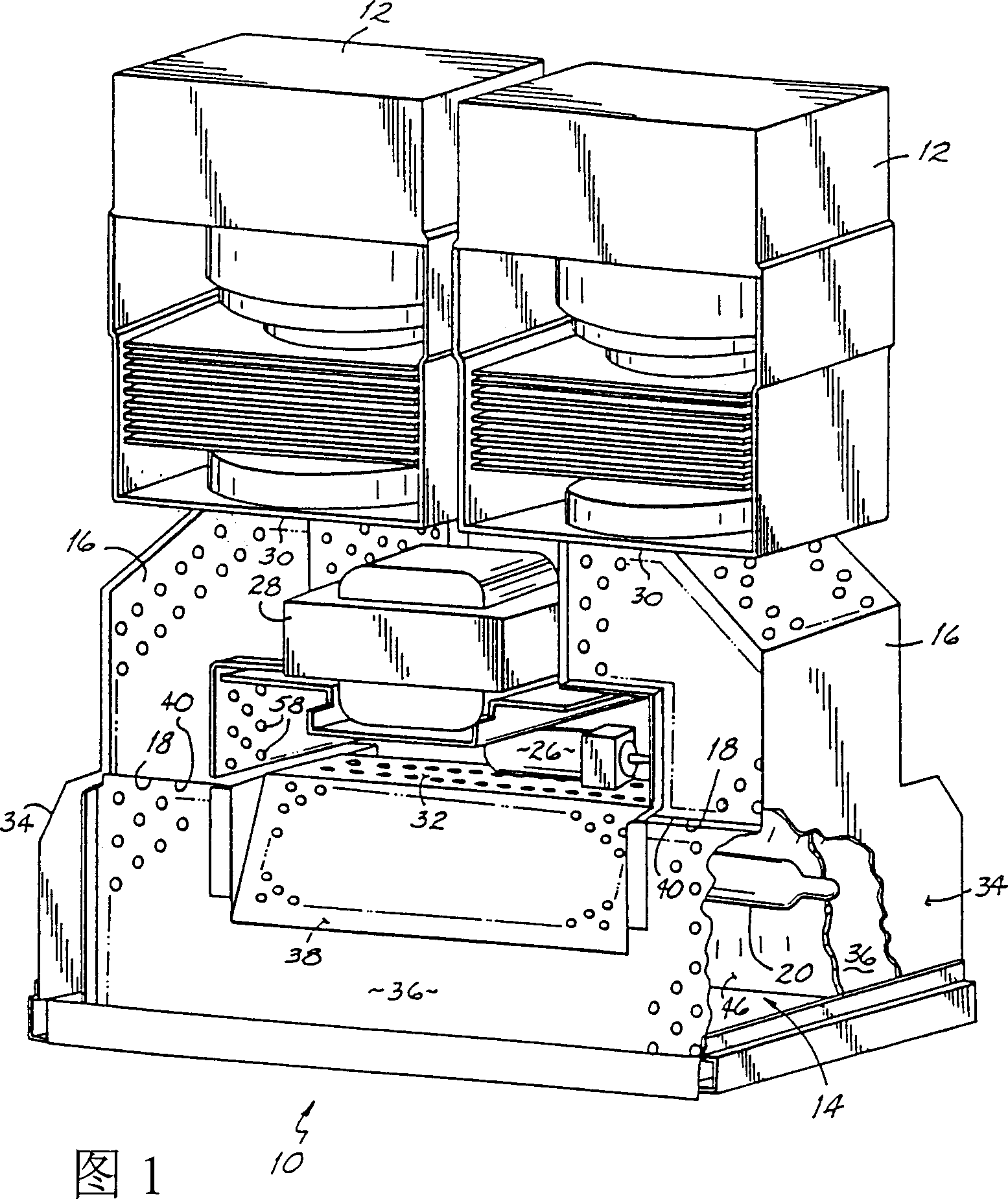
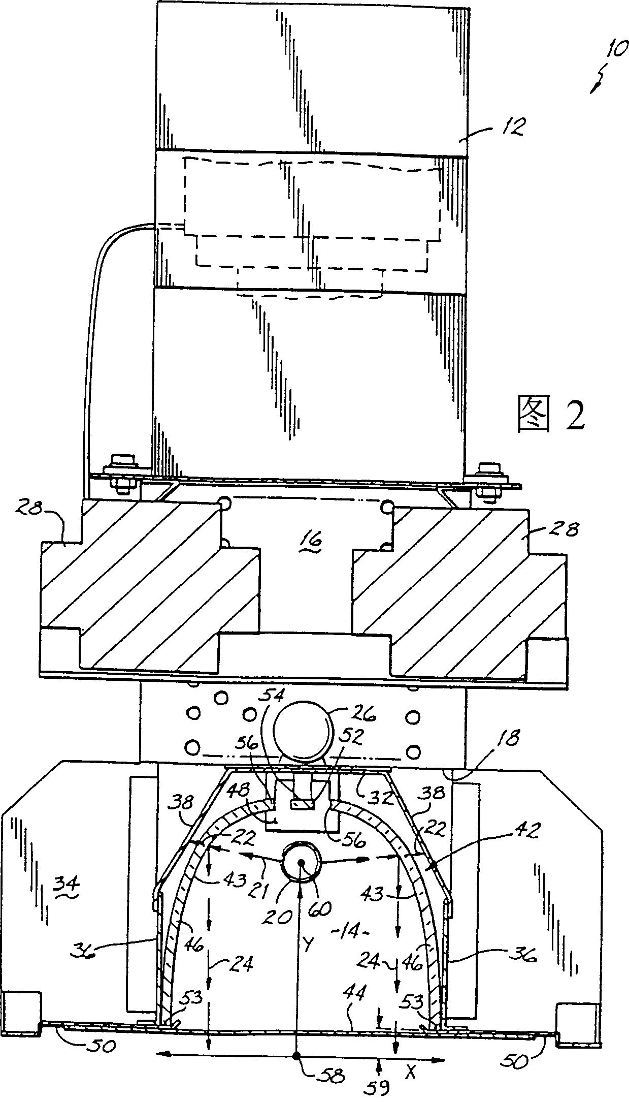
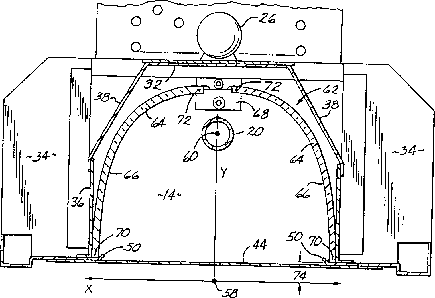
[0017] Referring to the drawings, there is shown a microwave excited ultraviolet ("UV") lamp system 10 in accordance with the principles of the present invention. Lamp system 10 includes a pair of microwave generators, shown as a pair of magnetrons 12 , connected by respective waveguides 16 to a longitudinally extending microwave chamber 14 . Each waveguide 16 has an outlet 18 connected to the upper end of the microwave chamber 14 . Microwave energy generated by the pair of microwave generators 12 is coupled to the microwave chamber 14 in a longitudinally spaced relationship near opposite upper ends of the chamber 14 . An electrodeless plasma bulb 20 in the form of a sealed, longitudinally extending tube is mounted within microwave chamber 14 and supported near the upper end of chamber 14, as is known in the art. Although not shown, it should be understood that the lamp system 10 is housed in an enclosure well known to those of ordinary skill in the art, and includes a source...


PUM


Abstract

A reflector for use in an ultraviolet or other type of lamp system having a plasma bulb. The reflector includes one or more longitudinally extending reflector panels having a characteristic shape that advantageously reflects ultraviolet radiation emanating from the bulb to provide a uniform irradiance over a relatively large surface area of a substrate. A substantial portion of each reflector panel has a characteristic shape described by the equation (x/a)<2+n>+(y/b)<2+m>=1, where a and b are constants and n and m are exponents that range between 0 and 2.

Description

technical field [0001] This invention relates to ultraviolet lamp systems, and more particularly to a reflector for use in such lamp systems to reflect ultraviolet light generated by a plasma bulb mounted within the system. Background technique [0002] A UV lamp system is used to couple microwave energy to an electrodeless lamp, such as a UV plasma bulb, mounted in the microwave cavity or chamber of the lamp system. In UV lamp heating or curing applications, one or more magnetrons are typically located in the lamp system to couple the microwave radiation to the plasma bulb within the microwave chamber. The magnetron is connected to the microwave chamber through a waveguide, and the waveguide includes an outlet connected to the upper end of the microwave chamber. When the plasma bulb is sufficiently excited by microwave energy, it will emit a spectrum of radiation with strong ultraviolet and infrared components through the bottom end of the microwave chamber towards the sub...

Claims


Application Information

Patent Timeline
Patent Type & Authority Applications(China)
IPC IPC(8): G21K5/00B01J19/12F21S2/00F21V7/00F21V7/04F21V7/22F21Y103/00F26B3/28G02B5/10G02B5/26G02B27/00
CPCF26B3/28G02B5/10H01J65/044F21V7/04
Inventor 理查德·G·克莱因詹姆斯·W·施米特科恩斯
Owner NORDSON CORP
Why Eureka
Try Eureka