Supercharge Your Innovation With Domain-Expert AI Agents!

Sheet separating method and device

A sheet material and conveying device technology, applied in transportation and packaging, thin material processing, printing, etc., can solve the problems of increasing equipment cost, complexity, and overall enlargement, and achieve the effect of simple structure

Inactive Publication Date: 2002-05-01
FUJIFILM CORP
View PDF1 Cites 0 Cited by
  • Summary
  • Abstract
  • Description
  • Claims
  • Application Information

AI Technical Summary

Problems solved by technology

[0011] However, it is difficult and complicated to set the switching timing of the damper 88 in accordance with the conveying speed of the sheet S and the length of the sheet, etc.
Since a dedicated large-scale conveyor belt is required to convey each sheet after separation, the overall size of the equipment is increased, and the equipment cost is likely to increase.

Method used


Image

  • Sheet separating method and device
  • Sheet separating method and device
  • Sheet separating method and device

Examples


Embodiment Construction

[0032] Hereinafter, an embodiment of the sheet separating device of the present invention will be described in detail with reference to the drawings.

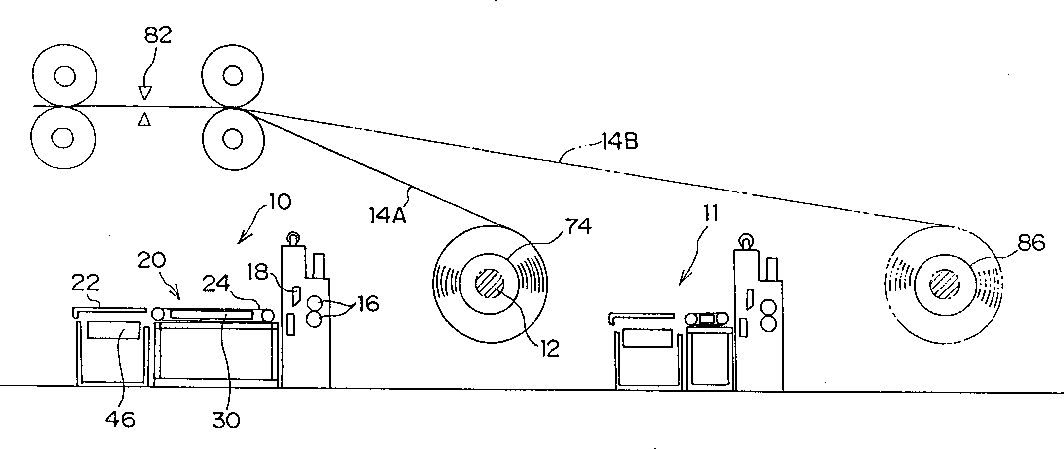
[0033] Such as image 3 As shown, two separating devices 10 and 11 are set in one production line, and the plates 14A and 14B are continuously rolled up and can be sampled. Since the separating devices 10 and 11 basically have the same structure, the left separating device 10 will be described here.

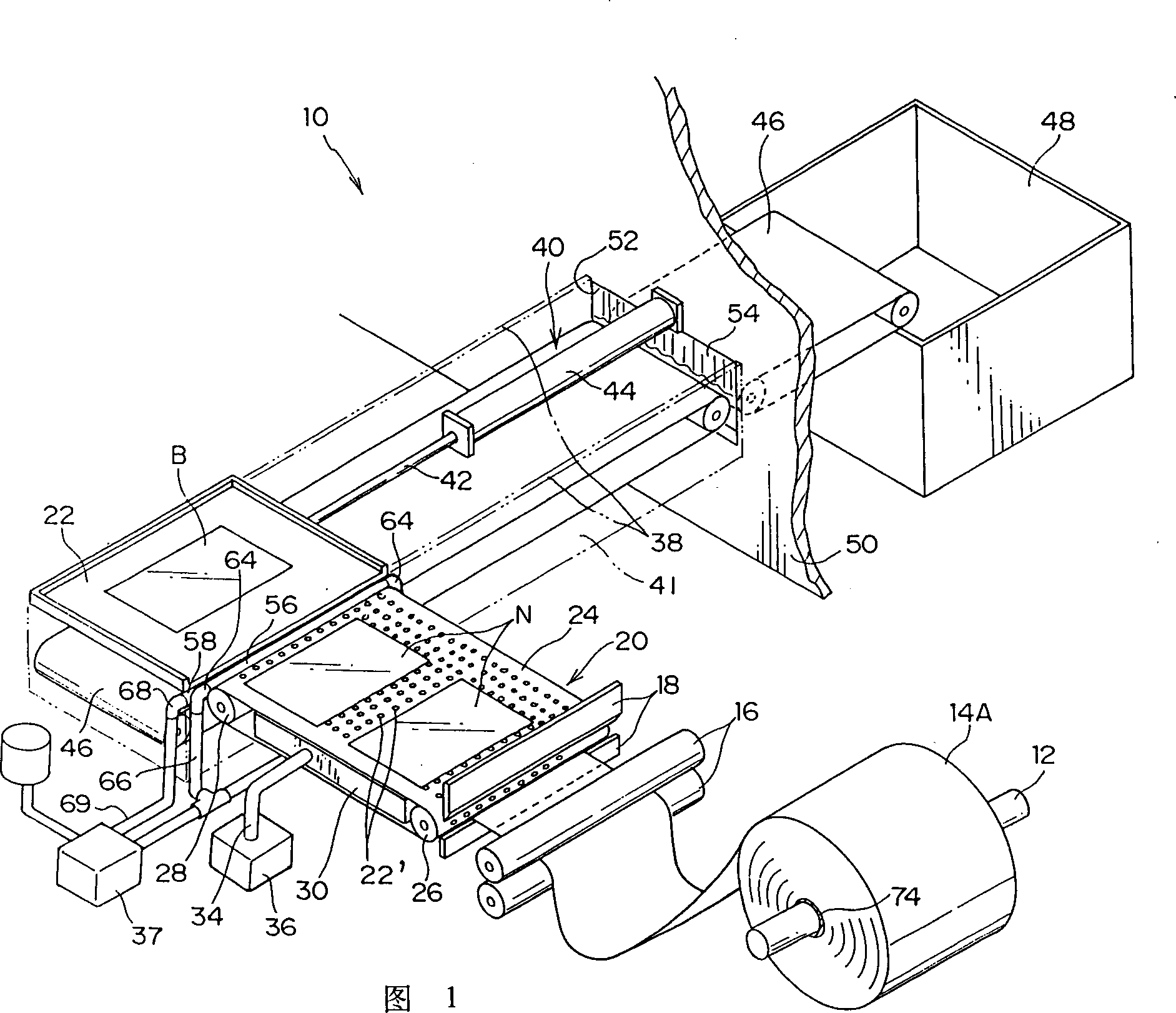
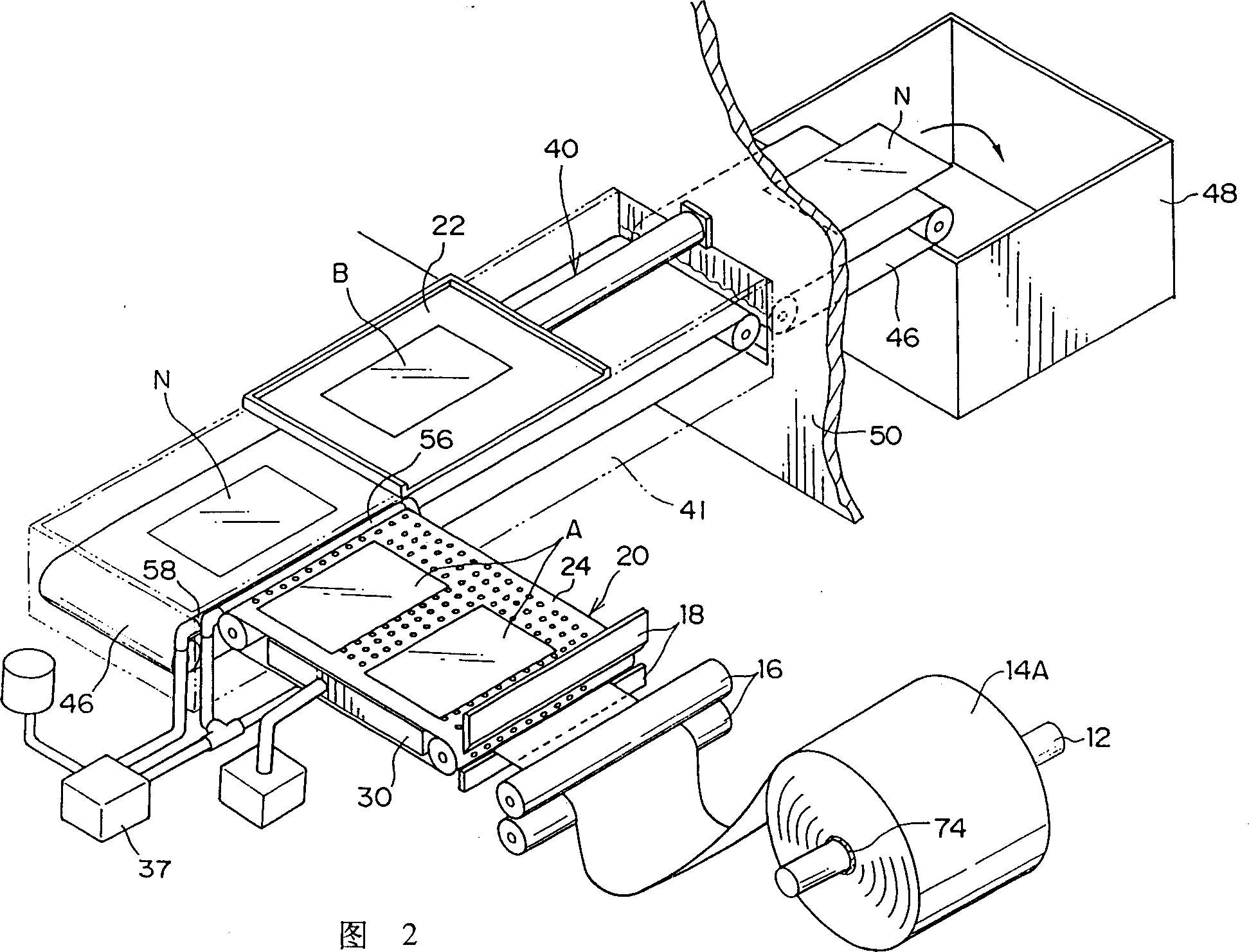
[0034] As shown in FIGS. 1 and 2, the plate 14A is wound on the reel 12 to form a roll 74, and the sample A, the NG slice NG, and the sample B are being cut out.

[0035] First, the plate is unrolled, nipped and conveyed by the feed roller 16, and conveyed to the cutter 18. A suction conveyor belt 20 is arranged downstream of the cutter 18, and the sheets A, NG, and B cut to a predetermined length by the cutter 18 are conveyed to the gathering table 22 by the suction conveyor belt 20.

[0036] The suction conveyor belt 20 has an endle...


PUM


Abstract

The invnetion is to automatically sort sample sheets from NG sheets with a simple mechanism without damaging any sheet. A web (14A) is cut into the sample sheets and the NG sheets by a cutter (18). Since the sheets are carried while sucked by a suction conveyor (20), they can be consistently carried without any damages. The carried sample sheets are transferred to a stacking table (22). The stacking table (22) is evacuated from a top part of an NG conveyor (46) disposed below the stocking table (22) by an air cylinder (40). By evacuating the stacking table (22), the NG sheets to be carried by the suction conveyor (20) are dropped onto the NG conveyor (46) and stacked. Thus, the sample sheets can be automatically sorted from the NG sheets without taking out the NG sheets from the stacking table (22) one by one.

Description

Technical field [0001] The invention relates to a method and a device for simply separating sampled (sampling) sheets. The separation is to ensure the quality of photosensitive lithographic printing plates. Background technique [0002] The photosensitive lithographic printing plate (hereinafter referred to as "plate") production line consists of surface treatment process, coating process and drying process. Specifically, as shown in Figures 8A and 8B, aluminum strip metal plates of different sizes and thicknesses (hereinafter referred to as "strip plates") are transported from the rolls 70 and 72 into the surface treatment process by the delivery device. After the coating process and the drying process, the winding shaft of the winding device is used to wind up into rolls 74 and 76. [0003] Usually, in order to ensure the quality of the roll plate, the sent front and back plate slices are taken as samples, and the quality of the samples is checked. [0004] In detail, as shown ...

Claims


Application Information

Patent Timeline
Patent Type & Authority Applications(China)
IPC IPC(8): B65H29/62B41N3/00B65H29/60B65H35/04
Inventor 青野胜利
Owner FUJIFILM CORP
Features
  • R&D
  • Intellectual Property
  • Life Sciences
  • Materials
  • Tech Scout
  • Unparalleled Data Quality
  • Higher Quality Content
  • 60% Fewer Hallucinations
Learn More