

Multi-frequency sharing array antenna
A technology for sharing antennas and antennas. It is applied to antenna arrays, antennas, and antenna arrays that are energized separately. It can solve the problems of radiation directivity distortion and antenna gain reduction in the front direction, so as to reduce the deterioration of radiation directivity and suppress excitation current. The occurrence of , the effect of suppressing the excitation current
- Summary
- Abstract
- Description
- Claims
- Application Information
AI Technical Summary
Problems solved by technology
Method used
Image

Examples
Embodiment 1
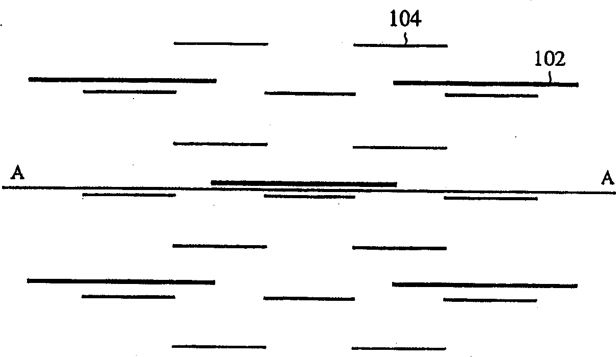
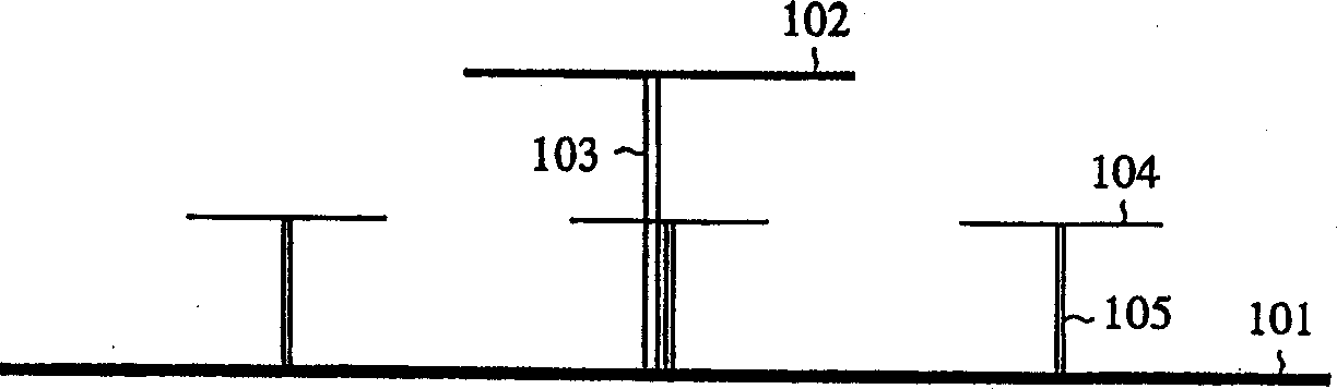
[0059] Figure 4 It is a top view showing the structure of the dual-frequency sharing antenna array according to Embodiment 1 of the present invention. Also, Figure 5 shows along Figure 4 Antenna array diagram seen on the vertical plane of line A-A. In the figure: 1 is a plane or curved ground conductor; 2 is a dipole antenna (wire antenna) composed of a dipole antenna unit (antenna unit part) that works with a relative frequency f1; 3 is the feeder of the dipole antenna 2 ; 4 is located on both sides of the feeder line 3, formed near the midpoint of the left and right dipole antenna units of the dipole antenna 2, forming a curved bend; 5 is a dipole antenna working at a frequency f2 higher than the frequency f1; 6 is the feeding line of the dipole antenna 5 .
[0060] Its working process is described below.
[0061] In the case of a common dipole antenna with two frequency bands in the same aperture, the dipole antenna working at a relatively low frequency f1 blocks the ...
Embodiment 2
[0073] Figure 12 It is a schematic structural diagram of a dipole antenna working at a relatively low frequency according to Embodiment 2 of the present invention. The same symbols as those in No. 6 denote the same or corresponding parts, so explanations are omitted. 11 is the gap at the feeding point of the dipole antenna; 12 is the starting point of the bellows 4; 13 is the end point of the bellows 4; 14 is a linear conductor that regards the dipole antenna as divided on a specific frequency. Compared with Embodiment 1, Embodiment 2 differs in that: the length of the bell curve set near the center of each dipole unit of the relatively low working frequency f1 of the dipole antenna is limited in this embodiment. In other words, in the present embodiment, the length of the crank is set to 1 / 4 of the wavelength of the radio wave of relatively higher frequency f2.
[0074] The operation process will be described below.
[0075] The situation of making the multi-frequency sha...
Embodiment 3
[0078] Figure 13 It is a schematic structural diagram of a dipole antenna working at a relatively low frequency according to Embodiment 3 of the present invention. The same symbols as those in No. 6 denote the same or corresponding parts, so explanations are omitted. The difference between Embodiment 3 and Embodiment 1 and Embodiment 2 is that the cranks on the left and right dipole units constituting the dipole antenna are not near the center but at any position. Also, the bellcrank formation position on the dipole subunit is determined by the distance L1 from the feeder line 3 to the bellcrank 4 and the distance L2 from the center of the bellcrank 4 to the end of the dipole unit.
[0079] The operation process will be described below.
[0080] Regarding the case of making the multi-frequency shared antenna array work at the relatively low frequency f1, it is the same as that of Embodiment 1, and the description is omitted. On the other hand, when operating at a relativel...
PUM
 Abstract
Description
Claims
Application Information