
Upper metal die with injection tube mouth having heating line fixing slot

A heating wire and metal mold technology, which is applied in the field of the upper metal mold with the heating wire fixing groove in the injection nozzle, can solve the problems of time-consuming, inconvenient operation, and great adverse industrial impact.

Inactive Publication Date: 2002-05-22
YUDO
View PDF0 Cites 1 Cited by
  • Summary
  • Abstract
  • Description
  • Claims
  • Application Information

AI Technical Summary

Problems solved by technology

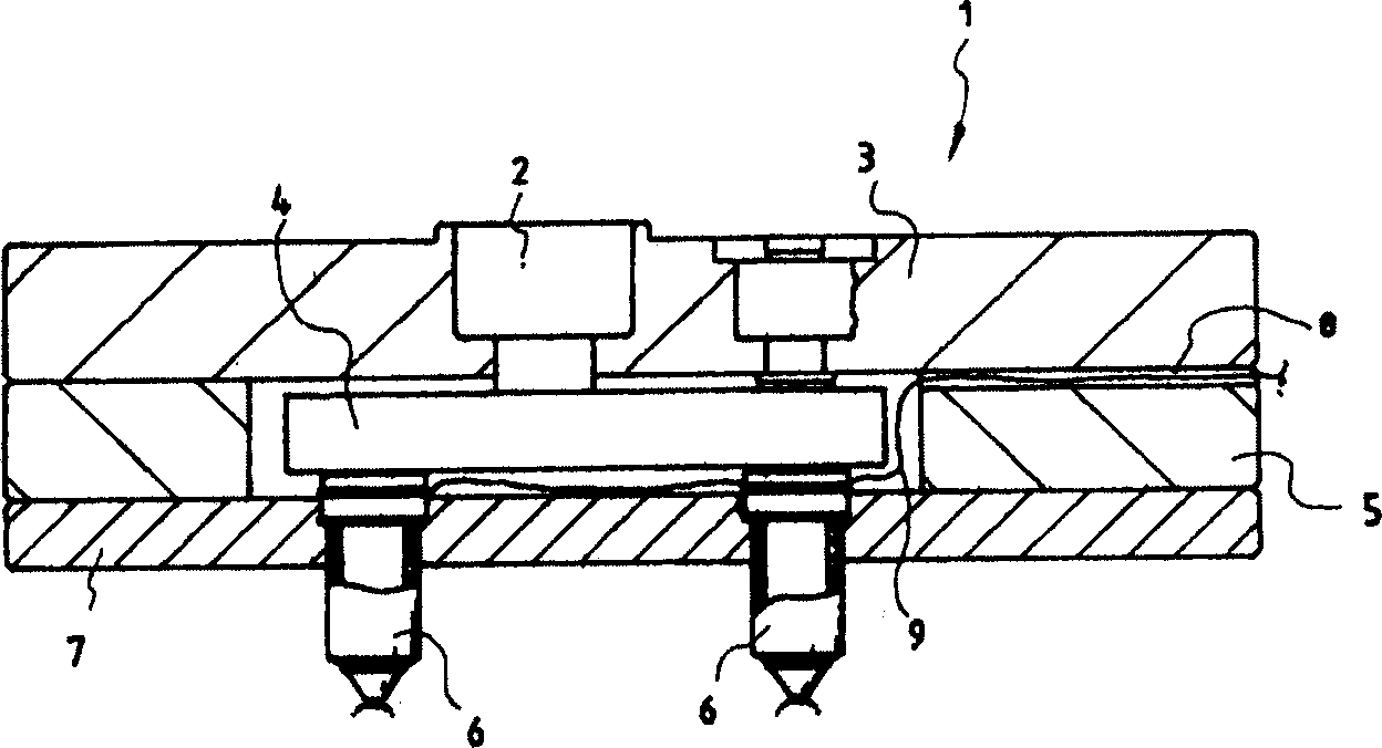
[0008] Therefore, there is a problem that repair work costs are high due to reasons such as inconvenient work and time-consuming.
In addition, the production line of synthetic resin products is also stopped in proportion to the repair time of the heating wire 9, so there is a problem that the longer the repair time, the greater the adverse effect on the industry.

Method used


Image

  • Upper metal die with injection tube mouth having heating line fixing slot
  • Upper metal die with injection tube mouth having heating line fixing slot
  • Upper metal die with injection tube mouth having heating line fixing slot

Examples


Embodiment Construction

[0014] Hereinafter, the configuration and operation of the present invention will be described in detail with reference to the drawings.

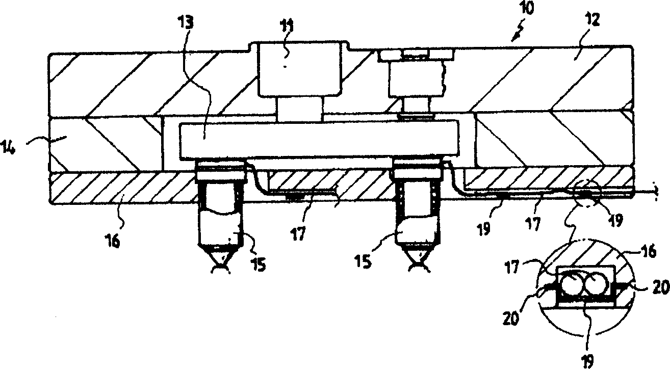
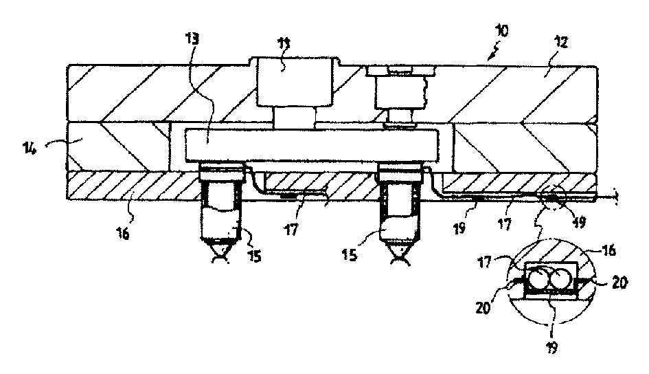
[0015] figure 2 It is a structural diagram of the upper mold of the injection molder of the present invention.

[0016] As shown in the figure, in the present invention, on the upper metal mold 10 of the injection molding machine, a cylinder box 12 with a connecting mechanism 11 is formed inside, and at the lower end of the cylinder box 12, a spiral distributor shell 14 is formed. Inside the device housing 14, a spiral distributor 13 is formed, and the above-mentioned connection mechanism 11 is connected with the spiral distributor 13.

[0017] At the lower end of the spiral distributor case 14, a nozzle case 16 is formed, and the nozzle case 16 is provided with an injection nozzle 15, and the injection nozzle 15 provided on the nozzle case 16 is connected to the spiral distributor 13. On one side of the lower end of the above-mentioned ...


PUM


Abstract

A top mold of an injection molding machine is disclosed. The top mold of this invention has a cylinder housing having a pouring gate, a manifold housing having a manifold and mounted on the lower surface of the cylinder housing, and a nozzle housing having an injection nozzle and mounted on the lower surface of the manifold housing. The top mold also has a heating wire guide hole formed on the lower surface of the nozzle housing. A heating wire extends from an external power source to the injection nozzle through the heating wire guide hole. A clip holding slit is formed on the sidewall of the heating wire guide hole. The top mold of this invention allows a user to easily and simply repair or replace a heating wire within a short period of time without entirely disassembling the top mold. This top mold is thus reduced in its maintenance cost, and reduces the time the injection molding process is stopped while repairing or replacing the heating wire, reduces the adverse effect about industry.

Description

technical field [0001] The present invention relates to a mold capable of easily fixing a heating wire of an injection nozzle provided on an upper mold of an injection molding machine, and particularly relates to an upper mold having a heating wire fixing groove for an injection nozzle, which The bottom surface of the spiral distributor forms a fixing groove, and the spiral distributor is combined with a plurality of injection nozzles provided inside the upper metal mold, and has a resin cavity inside, and is fixed by fixing the heating wires provided for heating the above nozzles. In the fixed groove, replacement of the screw distributor at the injection nozzle, or repair of the heating wire can be easily performed. Background technique [0002] Usually, an injection molding machine for injection molding a synthetic resin product is to put the synthetic resin raw material into a cylinder provided on one side, and inject it into a metal mold in a molten state by the cylinder...

Claims


Application Information

Patent Timeline
Patent Type & Authority Applications(China)
IPC IPC(8): B29C45/74B29C45/17B29C45/20B29C45/26B29C45/27
CPCB29C45/2737B29C45/1782B29C45/2738B29C45/26
Inventor 柳永熙
Owner YUDO
Learn More