Detection system of sheet glass for making display

A technology for inspection systems, flat glass, used in the field of inspection systems to solve problems such as soiling surfaces

Inactive Publication Date: 2002-06-19
巴斯勒公开股份有限公司
View PDF0 Cites 19 Cited by
  • Summary
  • Abstract
  • Description
  • Claims
  • Application Information

AI Technical Summary

Problems solved by technology

It is therefore not possible to avoid damage or soiling of the surface by rol...

Method used


Image

  • Detection system of sheet glass for making display
  • Detection system of sheet glass for making display
  • Detection system of sheet glass for making display

Examples


Embodiment Construction

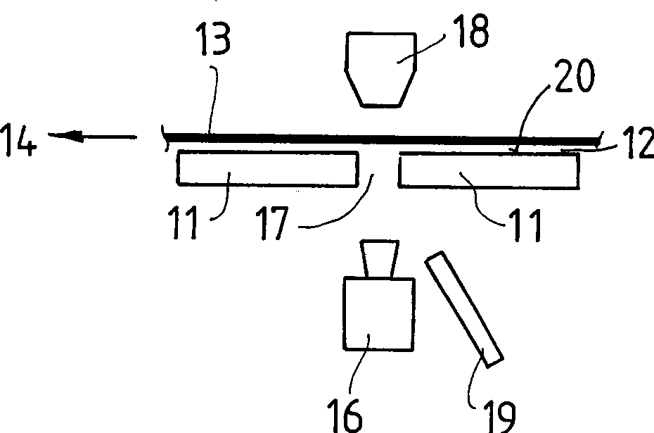
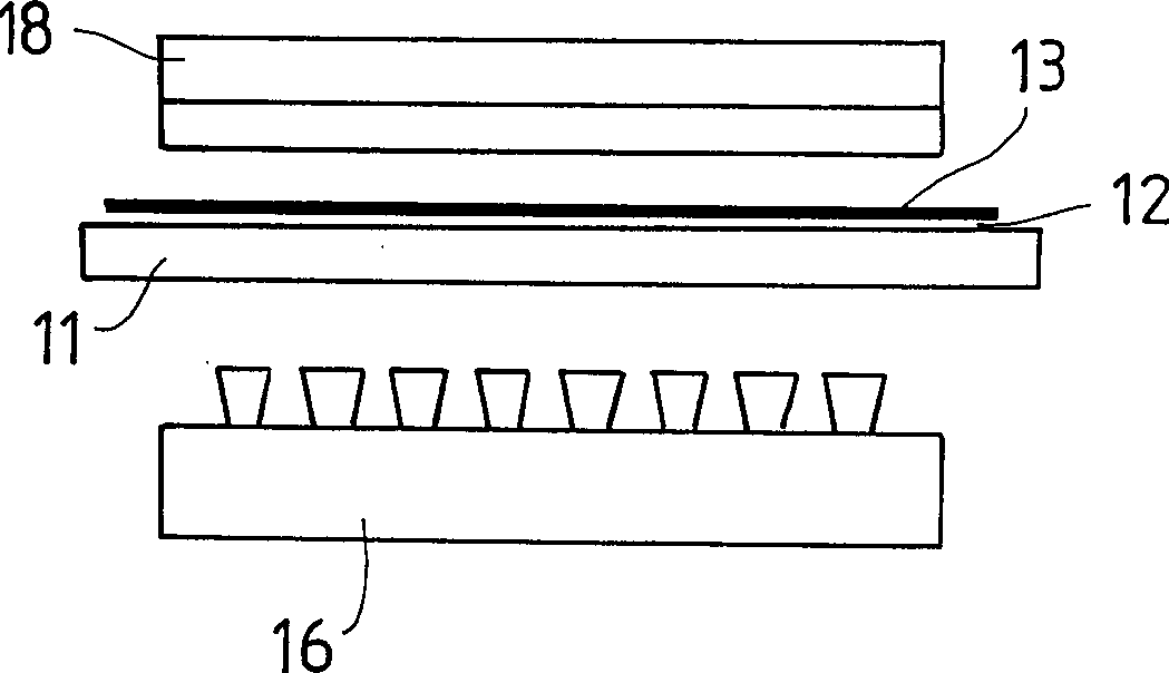
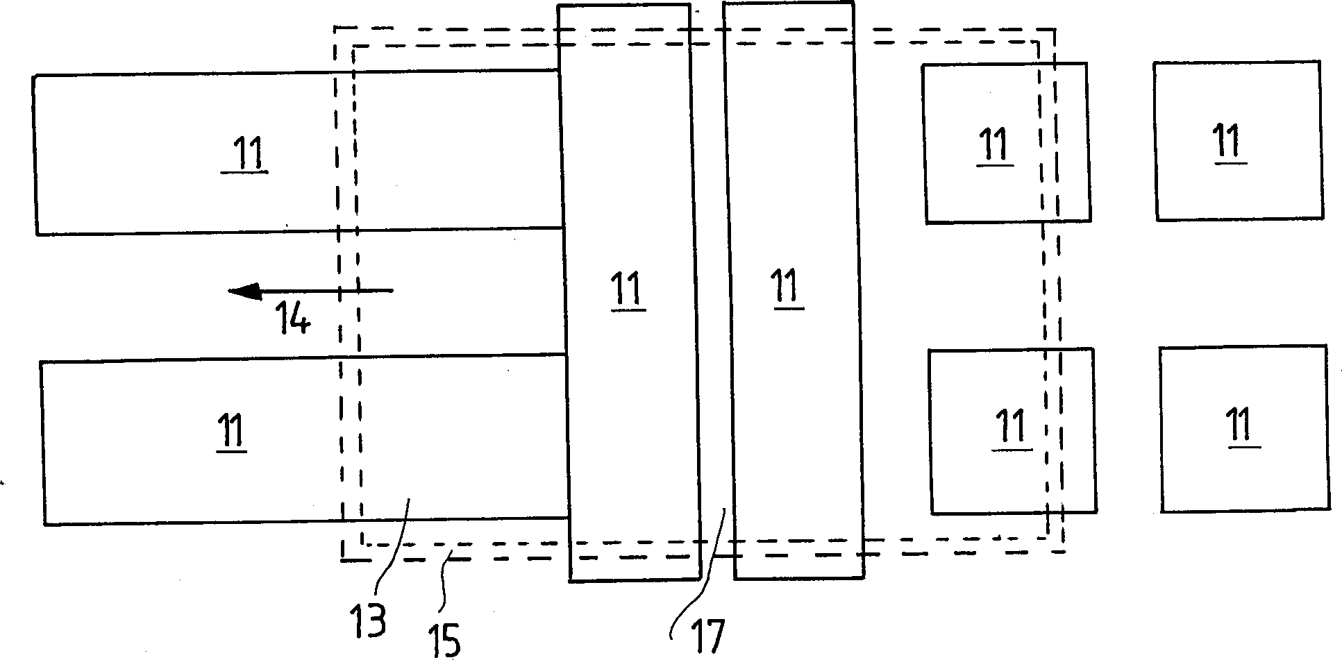
[0024] The inspection system shown in the figure has a plurality of plates 11 which can be fed with compressed air from their rear sides. In order to make the figure clear, half of the required air compressor and the casing for distributing the compressed air behind the panel and the pipelines for conveying the compressed air are not shown. Plate 11 is made of a porous sintered metal material. Air is thereby allowed to pass through the gaps in order to form the supporting air cushion 12 against or above the surface 20 of the object under examination.

[0025] The air cushion formed serves to support the flat glass 13 as it is moved past the scanning device by a not shown conveyor. The conveying movement takes place linearly in the direction of the arrow 14 . The board and air cushion are in such a position that they are arranged at an angle of 0° or inclined to almost vertical orientation. Here, the transfer device rests against the operating edge 15 of the plate glass.

...


PUM

PropertyMeasurementUnit
Sizeaaaaaaaaaa
Thicknessaaaaaaaaaa

Abstract

The present invention relates to a flat and thin object, and particularly to an inspecting system including at least a touch free detector which includes at least a camera, a lighting unit, and a conveyer to make an object move relatively, especially by an optical method for flat glass during display processing. The object can be held at a correct distance to the inspecting system by a clear thickness above an air cushion in the working area of the inspecting system. Therefore, the perfect transfer can be approached for the fragile flat glass of the display during inspecting.

Description

field of invention [0001] The invention relates to an inspection system for flat, thin objects, which has at least one non-contact optical scanning device, in particular with at least one camera and at least one lighting unit, and at least one device for scanning the object relative to The conveyor on which the scanning unit moves. In particular, the present invention relates to inspection systems for the manufacture of flat glass in the display industry, therefore, the following topics refer primarily to flat glass, but are not limited thereto. Background technique [0002] In the manufacture of flat glass, for example for display screens and similar items, it is necessary to inspect the glass for defects. This applies not only to transparent carrier materials, but also to applied coatings. The inspection system usually has an optical scanning device, in which at least one camera is illuminated by at least one illumination unit in bright field, dark field or in transmitte...

Claims


Application Information

Patent Timeline
IPC IPC(8): G01B11/30G01N21/896
CPCG01N21/896
Inventor 奥利弗·博恩霍尔兹贡特·加尔费德特特夫·哈根布鲁克沃尔弗拉姆·劳克斯
Owner 巴斯勒公开股份有限公司
Why Eureka
Try Eureka