Cyclone compressor
A scroll compressor and compression chamber technology, applied in the field of scroll compressors, can solve the problems of poor reliability of scroll compressors and the like
- Summary
- Abstract
- Description
- Claims
- Application Information
AI Technical Summary
Problems solved by technology
Method used
Image
Examples
no. 1 example
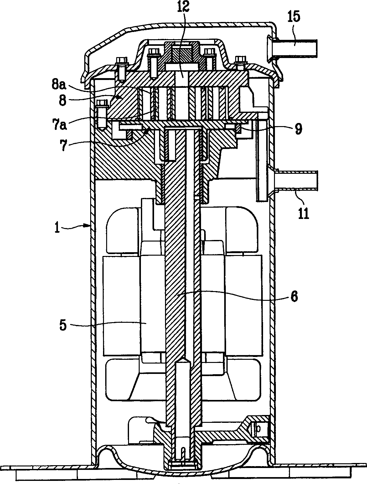
[0053] Figures 5A-5B Shows the steps of forming the first involute and the second involute for the orbiting scroll of the scroll compressor according to the first preferred embodiment of the present invention. Referring to this figure, steps of forming the first involute 101 and the second involute 102 are explained.
[0054] In order to form the moving scroll 100 (see Figure 7 ), need two involutes, namely the first involute 101 and the second involute 102.
[0055] like Figure 5A As shown, to form the first involute 101, an imaginary base circle 50 of radius 'a' is formed at the center of the X-axis and the Y-outer axis. Then, take a point on the circumference of the base circle 50 whose starting angle is 'α' relative to the X-axis as the starting point, and draw an inner involute 101a. like Figure 5A As shown, in order to form the thickness 't1' of the orbiting scroll 100 of the first involute 101, take a point on the circumference of the base circle 50 with a star...
no. 2 example
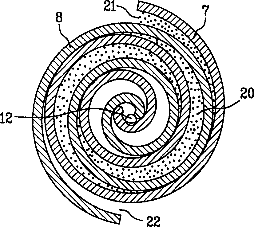
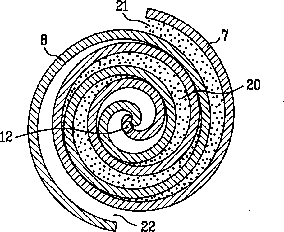
[0081] Figures 9A-9B Shows the steps of forming the fixed scroll and the movable scroll according to the second preferred embodiment of the present invention. Figure 10 Indicates the cooperation between the movable scroll and the fixed scroll formed according to the second preferred embodiment of the present invention. Referring to this figure, the structures of the movable scroll 400 and the fixed scroll 300 of the second embodiment of the present invention will be described in detail.
[0082] refer to Figure 9A , to form the orbiting scroll 400, an imaginary base circle 410 with a radius 'a' is formed at the center of the X-axis and the Y-outer axis. Then, take a point on the circumference of the base circle 410 relative to the starting angle 'α' of the X-axis as the starting point to form an inner involute 411 . like Figure 9A As shown, in order to form the thickness of the orbiting scroll 400, a point on the circumference of the base circle 410 relative to the sta...
no. 3 example
[0089] Figures 11A-11B Shows the steps of forming the fixed scroll and the movable scroll according to the third preferred embodiment of the present invention. Figure 12 It shows the cooperation state between the movable scroll and the fixed scroll formed according to the third preferred embodiment of the present invention. Referring to this figure, the structures of the movable scroll 600 and the fixed scroll 500 of the third embodiment of the present invention will be described in detail.
[0090] and Figure 9A , 9B Similar to the description above, in order to form the orbiting scroll 600, a point on the circumference of a base circle 610 with a radius 'a' relative to the starting angle 'β1' of the X-axis is taken as the starting point to form an inner involute 611. In order to form the thickness of the orbiting scroll 600, take a point on the circumference of the base circle 610 relative to the starting angle '-β1' of the X-axis as the starting point, and make an out...
PUM
 Abstract
Description
Claims
Application Information
 - R&D
- Intellectual Property
- Life Sciences
- Materials
- Tech Scout
- Unparalleled Data Quality
- Higher Quality Content
- 60% Fewer Hallucinations
Browse by: Latest US Patents, China's latest patents, Technical Efficacy Thesaurus, Application Domain, Technology Topic, Popular Technical Reports.
© 2025 PatSnap. All rights reserved.Legal|Privacy policy|Modern Slavery Act Transparency Statement|Sitemap|About US| Contact US: help@patsnap.com


