Method and equipment for reducing water evaporation

A technology for evaporating water and water consumption, which is applied in the field of recovering distilled water or other water vapor, which can solve the problems of reducing evaporative water and evaporative water loss, and achieve the effect of reducing water consumption and saving evaporative water consumption

Inactive Publication Date: 2002-07-03
侯铁信
View PDF0 Cites 14 Cited by
  • Summary
  • Abstract
  • Description
  • Claims
  • Application Information

AI Technical Summary

Problems solved by technology

At present, water saving in thermal power plants is aimed at wind blowing loss and sewage loss, and ...

Method used


Image

  • Method and equipment for reducing water evaporation
  • Method and equipment for reducing water evaporation
  • Method and equipment for reducing water evaporation

Examples


Embodiment Construction

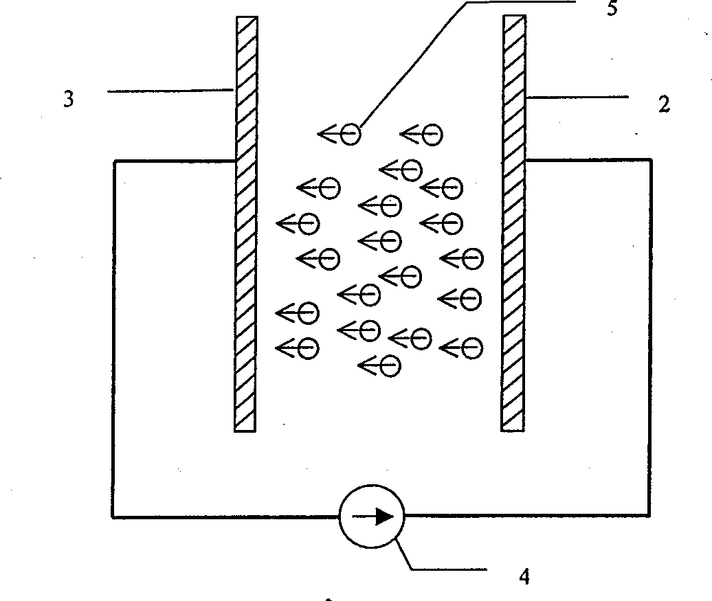
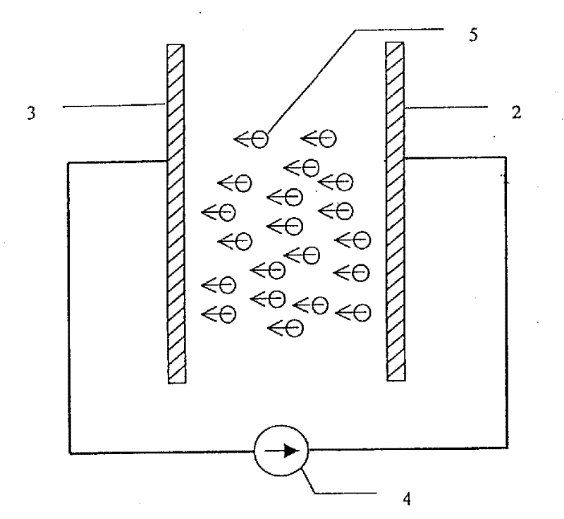
[0010] like figure 1 As shown, the principle of the present invention is: the evaporated water mist 5 is composed of countless tiny water droplets. When these tiny water particles pass through a high-voltage electric field, they are charged and become charged water particles. Under the action of the electric field, the charged micro-water particles move to the opposite electrode and finally reach the opposite electrode. When the positively charged micro-water particles reach the electrode to a certain concentration, a water film is formed until it starts to flow, which can be recovered by containers or pipes. These are the water on the electrodes. The high-voltage power supply can be a high-voltage DC power supply or a low-frequency high-voltage AC power supply. The electrodes can be designed into arbitrary geometric shapes according to the structural characteristics of the equipment.

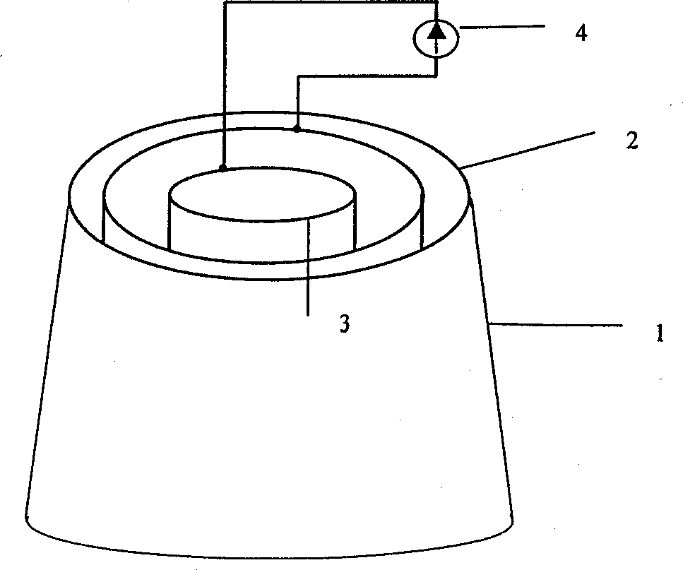
[0011] like figure 2 As shown, it is a cooling tower of a power plant, 1-cooling tower...


PUM


Abstract

A method and equipment for decreasing the loss of vapour water features that at least two electrodes are arranged in the space or channel, where water vapour moves, a high voltage is applied across said electrodes to generate a high-voltage electric field and a water collecting container or pipeline is arraged under the electrode. After the micro water particals are charged by said electric field, they move toward electrode and than collected. It can save wawter by more than 60%.

Description

technical field [0001] The invention belongs to water-saving technology, and in particular relates to a method and a device for recovering distilled water or other vapors. Background technique [0002] The circulating cooling water of existing thermal power plants is greatly lost due to evaporation, wind blowing, sewage discharge, etc., which is the main reason for the high water consumption of thermal power plants. It is difficult to reduce the above losses. Under normal circumstances, the circulating water of the cooling tower of a thermal power plant loses about 2% of the total water due to evaporation, the wind loss is less than 0.5%, and the sewage loss is about 1%. . At present, the water saving of thermal power plants is aimed at wind blowing loss and sewage loss, and no method has been found to reduce the evaporation water consumption, so that the evaporation water is lost in vain. In 2000, the national thermal power plants lost about 2 b...

Claims


Application Information

Patent Timeline
IPC IPC(8): B03C3/40F28C1/02
Inventor 侯铁信
Owner 侯铁信
Why Eureka
Try Eureka