
Ion generator for ion beam radiator

A technology for generating devices and irradiation devices, applied to the improvement of devices, and to the field of ion beam irradiation devices

Inactive Publication Date: 2002-07-03
日新意旺机械股份会社
View PDF0 Cites 1 Cited by
  • Summary
  • Abstract
  • Description
  • Claims
  • Application Information

AI Technical Summary

Problems solved by technology

However, related art devices can hardly meet such requirements

Method used


Image

  • Ion generator for ion beam radiator
  • Ion generator for ion beam radiator
  • Ion generator for ion beam radiator

Examples


Embodiment Construction

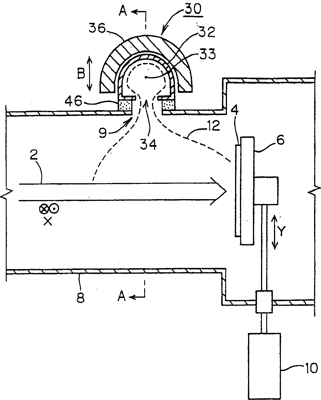
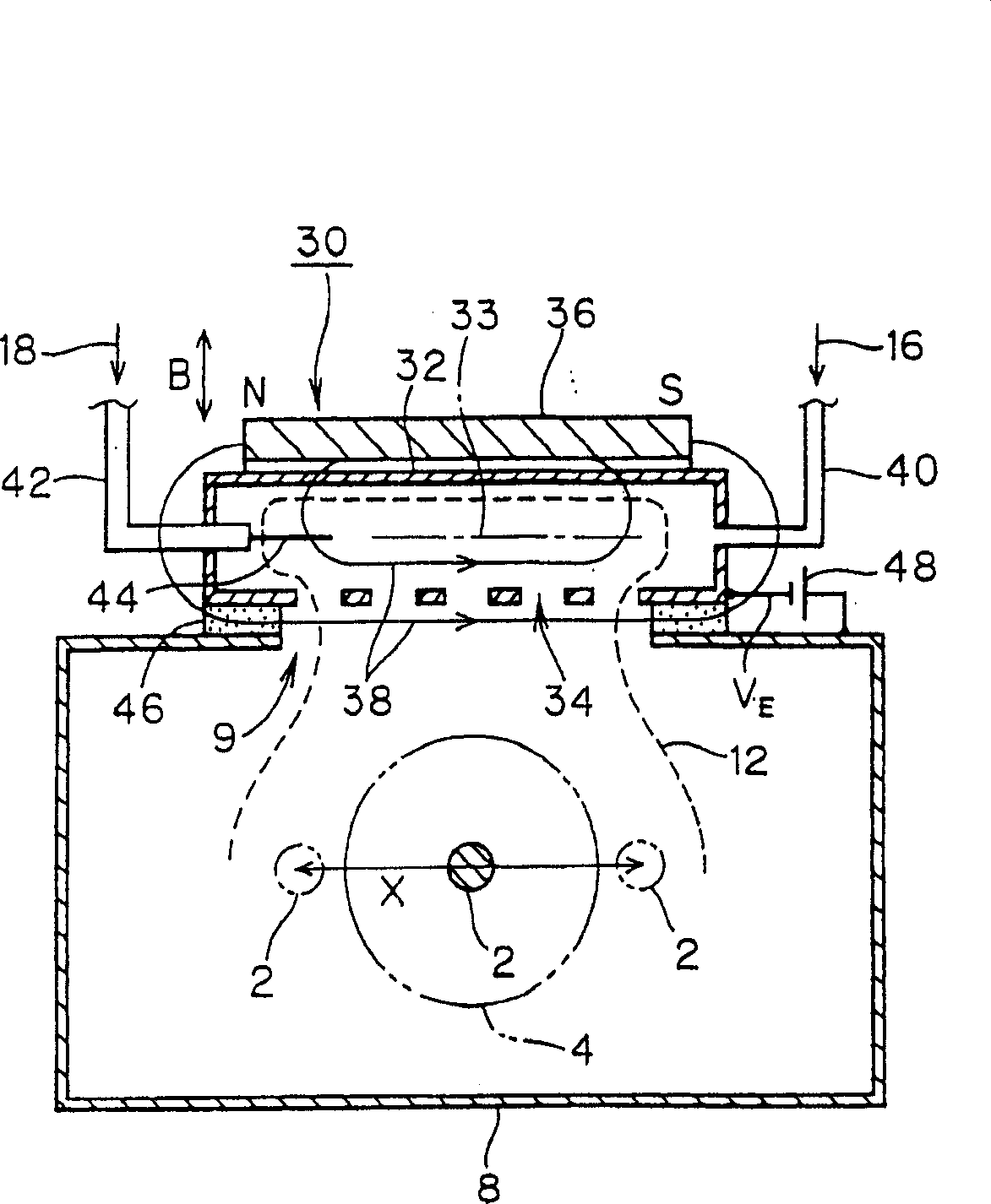
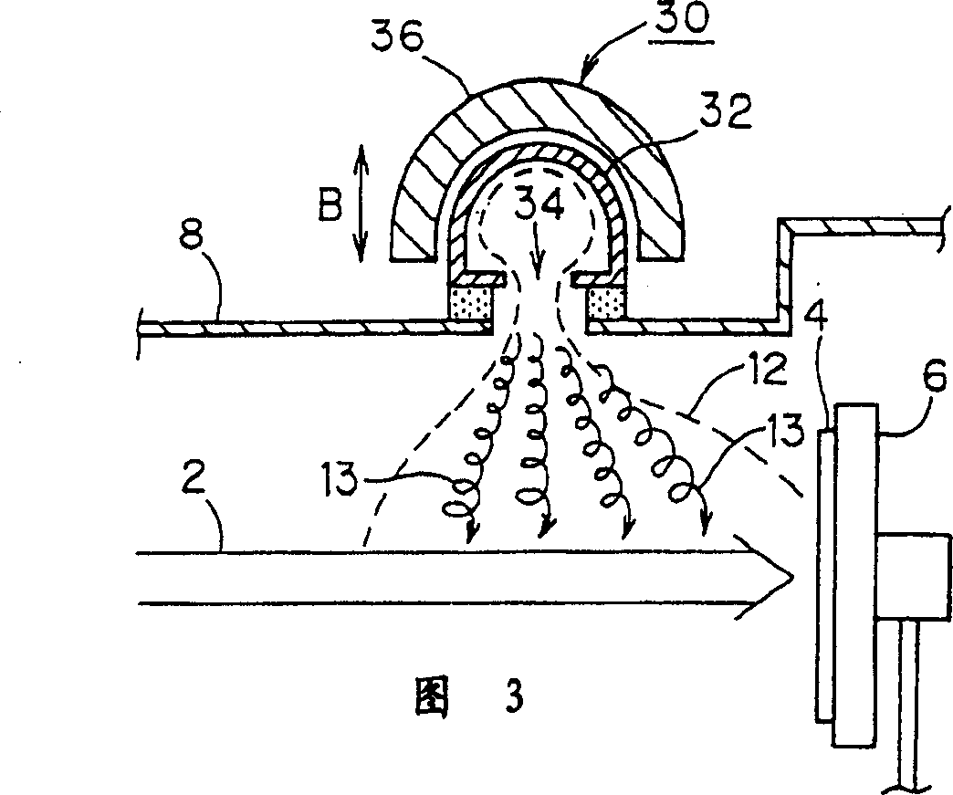
[0037] figure 1 is a longitudinal sectional view of an ion beam irradiation apparatus constructed according to the present invention. figure 2 yes figure 1 Transverse section in direction A-A. In these figures, the same reference numerals will be used for naming Figure 9 The same or equivalent parts of the Figure 9 The related art is shown. A description will follow, emphasizing the differences from the related art.

[0038] In the ion beam irradiation apparatus, a radio frequency discharge type plasma generating device 30 is installed outside the vacuum chamber 8 instead of the related art plasma generating device 20 , and the vacuum chamber is placed near the substrate 4 . In an embodiment, insulating material 46 is interposed between the plasma generating means and the vacuum chamber.

[0039] The plasma generating device 30 includes a plasma generating chamber 32 extending along an axis 33 extending along the scanning direction X of the ion beam 2, and the upper p...


PUM


Abstract

An ion beam irradiation apparatus is provided with a plasma production device 30 which produces a plasma 12 through the radio frequency discharge and supplies the produced plasma in the vicinity of the substrate 4. The plasma production device 30 includes a plasma producing chamber 32 being elongated along an axis 33 extending in scanning directions X in which the ion beam is moved; a plasma emission hole 34 being provided in a side thereof and elongated along the axis 33 of the plasma producing chamber; and a magnet 36 provided outside the plasma producing chamber 32 for producing a magnetic field having a direction along the axis 33. The magnetic field developed by the magnet 36 contains a magnetic field which has a direction along the axis and bends to the substrate ions contained in the plasma 12 emitted from a plasma emission hole 34.

Description

technical field [0001] The invention relates to an ion generating device and an ion beam irradiating device. The ion beam irradiating device is used to complete a process of implanting ions into the substrate by irradiating the substrate with the ion beam. More particularly, the present invention relates to improvements in apparatus for suppressing cumulative charging on a substrate when the substrate is irradiated with an ion beam. Hereafter the cumulative charge is called electrification. Background technique [0002] There is a proposal to suppress the charging of the substrate when the substrate is irradiated with ion beams. Plasma generated by the plasma generating means is supplied to the vicinity of the substrate. Electrons included in the plasma are used to neutralize positive charges generated by ion beam irradiation. The proposed technique supplies low energy electrons to the substrate when compared with techniques using secondary electrons,...

Claims


Application Information

Patent Timeline
IPC IPC(8): C23C14/48H01J27/16H01J37/08H01J37/317H01L21/265
CPCH01J2237/0041H01J37/3171
Inventor 滨本成显酒井滋树
Owner 日新意旺机械股份会社
Learn More