Non-return valve

一种单向阀、阀体的技术,应用在隔膜阀、控制阀、阀装置等方向,能够解决易于出现故障、成本高、阀门工作复杂等问题

Inactive Publication Date: 2002-07-24
AIPWAN CO LTD
View PDF0 Cites 45 Cited by
  • Summary
  • Abstract
  • Description
  • Claims
  • Application Information

AI Technical Summary

Problems solved by technology

[0005] ii) the valve 1 comprises relatively complex machined elements at a relatively high cost; and
[0006] iii) The valve works complex and thus prone to failure when working

Method used


Image

  • Non-return valve
  • Non-return valve
  • Non-return valve

Examples


Embodiment Construction

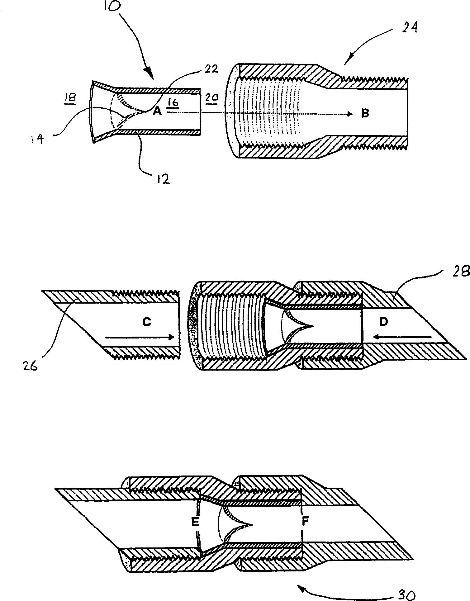
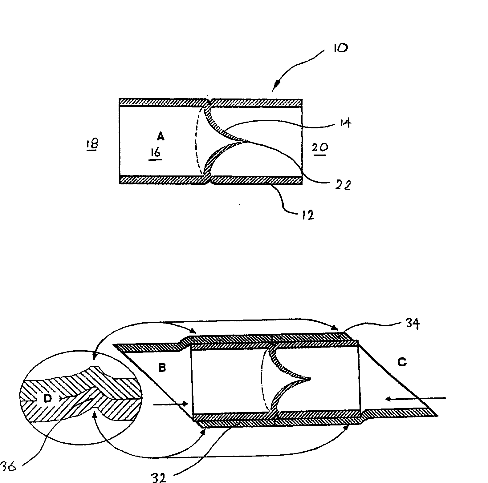
[0045] Such as Figures 2 to 5 As shown, various embodiments of a one-way valve, generally indicated at 10, constructed in accordance with an aspect of the present invention are shown. For ease of reference and to avoid repetition, similar elements are identified with the same reference numerals.

[0046] In each example, the one-way valve 10 includes a valve body 12 and a valve membrane 14 . Valve body 12 is generally tubular and includes an elongated passage 16 defining an inlet and an outlet at opposite ends 18 and 20 thereof, respectively.

[0047] The one-way valve 10 of these embodiments is molded from a polymeric material, preferably an elastomer such as rubber or a nylon-based material. Selection of suitable materials for valve 10 will be apparent to those skilled in the art without trial and experiment. The valve membrane 14 is a conical membrane formed integrally with the tubular valve body 12 . Diaphragm 14 is configured as a generally conical member having a re...


PUM


Abstract

A non-return valve (10), typically of commonly called duckbill valve shape, comprising a valve body (12) and a valve membrane (14). The valve body (12) is generally tubular and includes an elongate passageway (16) with inlet (18) and outlet (20) at opposing ends. The valve membrane (14) is of a generally conical-shaped diaphragm formed integrally with the valve body (12). The diaphragm (14) has a collapsible opening or aperture (22) located at or adjacent the cones apex. The conical diaphragm (14) is oriented with its apex pointing downstream. The resiliently flexible material from which the diaphragm (14) is constructed, ensures that the diaphragm (14) in a collapsed condition obstructs or closes the aperture (22) to prevent fluid flowing in a reverse direction, i.e. backflow towards the inlet. Pressurisation of fluid within the passageway (16) on the inlet (18) side of the diaphragm (14 ), deflects the diaphragm to open the aperture (22) so that fluid can flow through the passageway from the inlet (18) to the outlet (20) only. A membrane permeable in one direction only can also be made from a panel or sheeting incorporating many such collapsible non-return duckbill valves on the surface of the panel or sheet.

Description

technical field [0001] The present invention relates generally to a one-way valve, such as that used on pneumatic tires, and to membranes that are permeable in only one direction. Background technique [0002] Check valves are common in industry and households, and are abundant especially in pneumatic tires. figure 1 Various elements of a conventional pneumatic check valve 1 are shown. The valve 1 comprises an access sleeve 2 threaded into the valve stem of a tire (not shown). The access sleeve 2 houses a shaft 3 along which the valve element 4 is slidably movable. The valve element 4 biases the seat 5 of the sleeve 2 under the force of the compression spring 6 , thereby closing the valve 1 . A spring retainer 7 is attached to one end of the shaft in order to fix the compression spring 6 . Pressurization of the non-return valve 1 releases the valve element 4 from the seat 5, allowing the tire to be inflated. [0003] The traditional pneumatic che...

Claims


Application Information

Patent Timeline
Patent Type & Authority Applications(China)
IPC IPC(8): F16K15/14F16K15/20
CPCF16K15/147Y10T137/88054Y10T137/7838Y10T137/7882Y10T137/7837F16K7/07B60C29/06F16K15/1401F16K15/1472F16K15/145
Inventor 戴维·霍顿
Owner AIPWAN CO LTD
Why Eureka
Try Eureka