Synchronous timing calibrating circuit and method

A technology for synchronizing timing and correcting circuits, applied in the directions of synchronizing devices, synchronizing devices, radio/induction link selection and arrangement, etc., which can solve the problems of increased computational processing, circuit scale and correction processing.

Inactive Publication Date: 2002-08-14
NEC ELECTRONICS CORP
View PDF0 Cites 4 Cited by
  • Summary
  • Abstract
  • Description
  • Claims
  • Application Information

AI Technical Summary

Problems solved by technology

Moreover, since each associated device 105 must 1 -105 64 Perform calculation processing, so the amount of calculation processing increases as the window width increases
[0016] In the conventional synchronous timing correction circuit, there is a problem that the circuit scale and correction processing amount will increase because the number of correlating devices that coincide with the window width determined from the maximum frequency deviation is required

Method used


Image

  • Synchronous timing calibrating circuit and method
  • Synchronous timing calibrating circuit and method
  • Synchronous timing calibrating circuit and method

Examples


no. 1 example

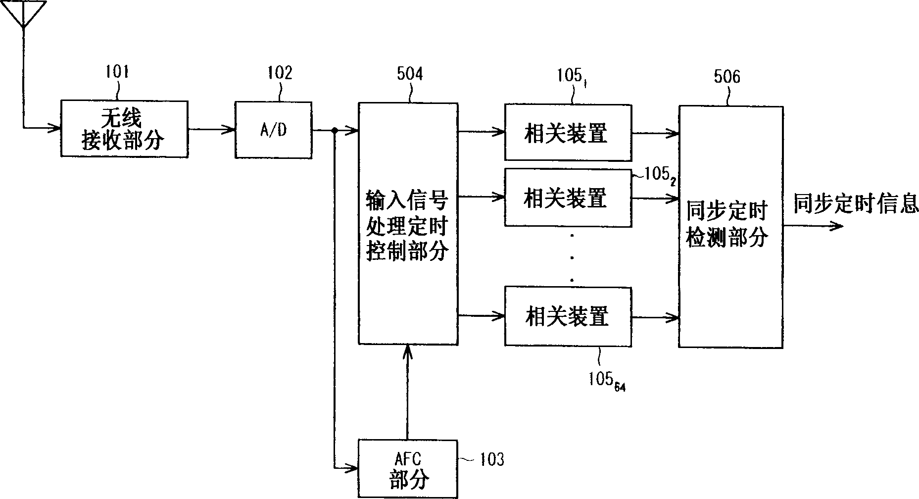
[0036] Figure 4 is a block diagram showing the structure of a CDMA receiver having a synchronous timing correction circuit according to the first embodiment of the present invention. Figure 4 1, the same constituent units or parts as in FIG. 1 are assigned the same reference numerals as in FIG. 1, and explanations thereof are omitted.

[0037] The synchronization timing correction circuit of this embodiment includes an input signal processing timing control section 104 having a window moving means 107, a correlation means 105 1 -105 8 , and a synchronization timing detection section 106 having an offset judging means 108.

[0038]The offset judging means 108 is obtained from each correlation means 105 by comparing with each other 1 -105 8 Correlation value, detect the offset and offset direction between the center value of the currently set window frequency and the synchronization timing (the maximum timing of the synchronization value) that can obtain the maximum correlat...

no. 2 example

[0052] Next, a synchronous timing correction circuit of a second embodiment of the present invention will be explained. The synchronous timing correction circuit in this embodiment is almost the same in structure as the first embodiment, but the difference between these two synchronous timing circuits lies in the difference in the determination method for determining the offset by the offset judging means 108 .

[0053] Next, an offset judgment method of the synchronous timing correction circuit in this second embodiment will be explained.

[0054] In the offset judging method of this embodiment, a judgment value Y(n) as a criterion of whether the window frequency center value should be changed is calculated according to the following equation (1), when the judgment value Y(n) exceeds a predetermined reference value , to change the frequency center value of the window.

[0055] Y(n)=Z×Y(n-1)+(1-Z)×T

[0056] Among them, Y(n) is the judgment value of this time, Y(n-1) is the ...


PUM


Abstract

Means (108) for judging an amount of deviation compares correlation values from respective correlating devices 1051 to 1058 with one another to detect a deviation amount and a deviation direction of a frequency central value currently set from a synchronization timing at which the maximum correlation value can be obtained and outputs a window position changing signal to window moving means 107. The window moving means 107 performs a change of the central frequency value of a window width on the basis of the window position changing signal from the deviation amount judging means 108. When the correlation value maximum timing moves from the central frequency due to an AFC error, the position of the window itself is moved corresponding to the movement of the correlation value maximum timing so that the correlation value maximum timing is prevented from deviating from the window even when the window width is made narrow.

Description

field of invention [0001] The present invention relates to a mobile communication system using wideband code division multiple access (hereinafter referred to as W-CDMA) technology, in particular to a synchronous timing correction circuit and method thereof, which are used to correct the synchronous timing of a base station that has been captured once. background of the invention [0002] In recent years, as a communication system for a mobile communication system, attention has been directed to a CDMA communication system which is less subject to interference or congestion. A CDMA system is a system in which, on the transmitting side, user signals to be transmitted are transmitted as spread signals in a spread spectrum manner, and on the receiving side, inverse spreading is performed using the same spreading code as the spread signals to obtain Raw user signal. For this reason, in the CDMA system, if the phase synchronization of the spreading code sequence between the tran...

Claims


Application Information

Patent Timeline
Patent Type & Authority Applications(China)
IPC IPC(8): H04B1/707H04B1/7085H04B7/26H04L7/00H04W56/00
CPCH04B1/7085H04B1/709
Inventor 村本公男
Owner NEC ELECTRONICS CORP
Why Eureka
Try Eureka