Steel bar splicing device implantation welding construction method

A technology of connectors and construction methods, which is applied in the direction of manufacturing tools, welding equipment, workpiece edges, etc., can solve problems such as insufficient bonding strength, time and manpower consumption, and difficulty in bearing stress, so as to shorten construction time, save manpower, and The effect of high quality and reliability

Inactive Publication Date: 2002-09-04
王台钦 +1
View PDF0 Cites 3 Cited by
  • Summary
  • Abstract
  • Description
  • Claims
  • Application Information

AI Technical Summary

Problems solved by technology

[0002] At present, the welding construction method of the steel bar connector used in general buildings, such as figure 1 , 2 As shown, it is mainly at the bottom of the steel bar adapter 1, using the method of manual electric welding, one by one to weld the steel bar adapter 1 on the surface of the general steel structure A, and then on the surface of the steel bar adapter 1 The steel bar B is screwed into the screw hole 10, so that the purpose of connecting the steel bar B can be achieved. However, in the above-mentioned construction method, because the bottom of the steel bar connector 1 is only partially fused with the welding spot C near the circumference, it does not completely cover it. The bottom area of ​​the entire steel bar coupler 1, therefore, only by a circle of solder joints C, its bonding strength is obviously insufficient, it is difficult to bear a large stress, and it is easy to cause the risk of fracture and separation, and this welding method is quite time-consuming and labor-intensive. Manpower, and increase the cost of construction

Method used


Image

  • Steel bar splicing device implantation welding construction method
  • Steel bar splicing device implantation welding construction method
  • Steel bar splicing device implantation welding construction method

Examples


Embodiment Construction

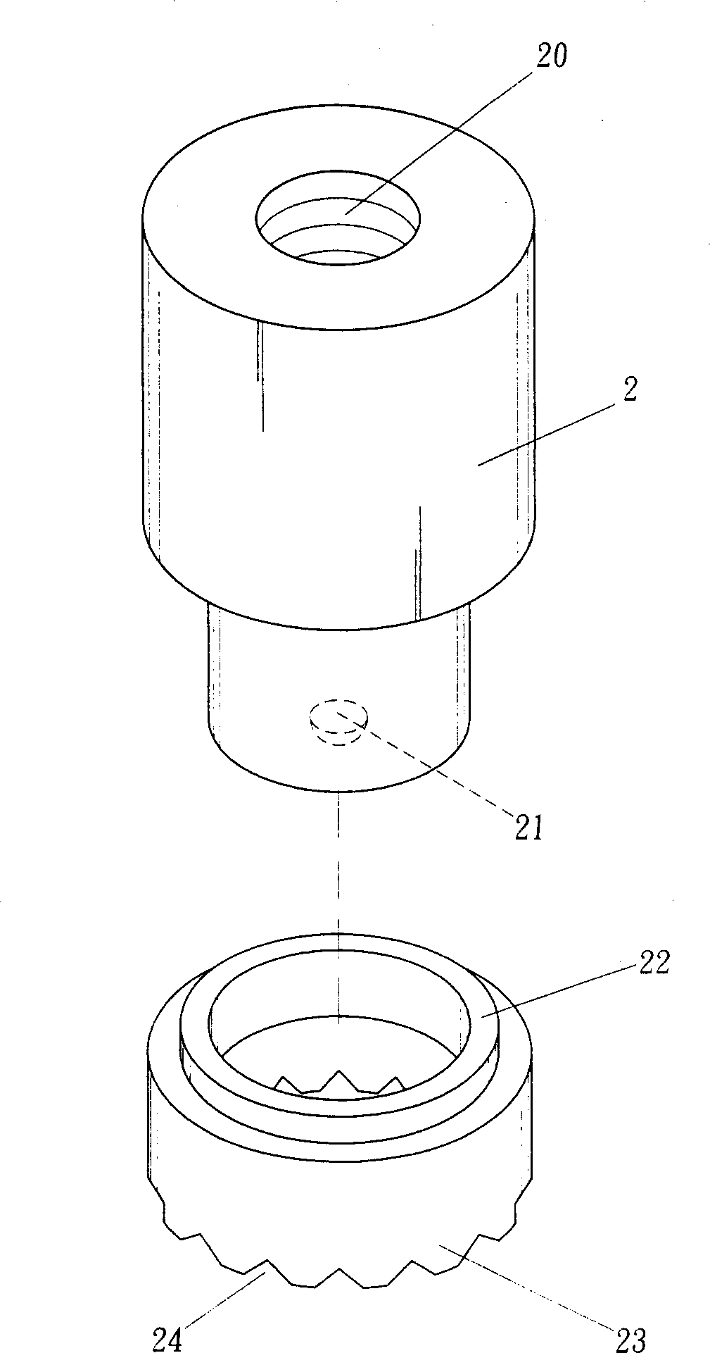
[0015] refer to image 3 , 4 As shown, the present invention is mainly provided with a screw hole 20 at the top of the steel bar connector 2, and a bead-shaped welding particle 21 is implanted at the bottom thereof, and the welding particle 21 is made of aluminum alloy, and then A protective ring 22 is inserted outside the steel bar connector 2. The protective ring 22 is made of materials such as high-temperature-resistant ceramics. A protective body 23 is arranged around the protective ring 22. Several wave-shaped Air vent 24.

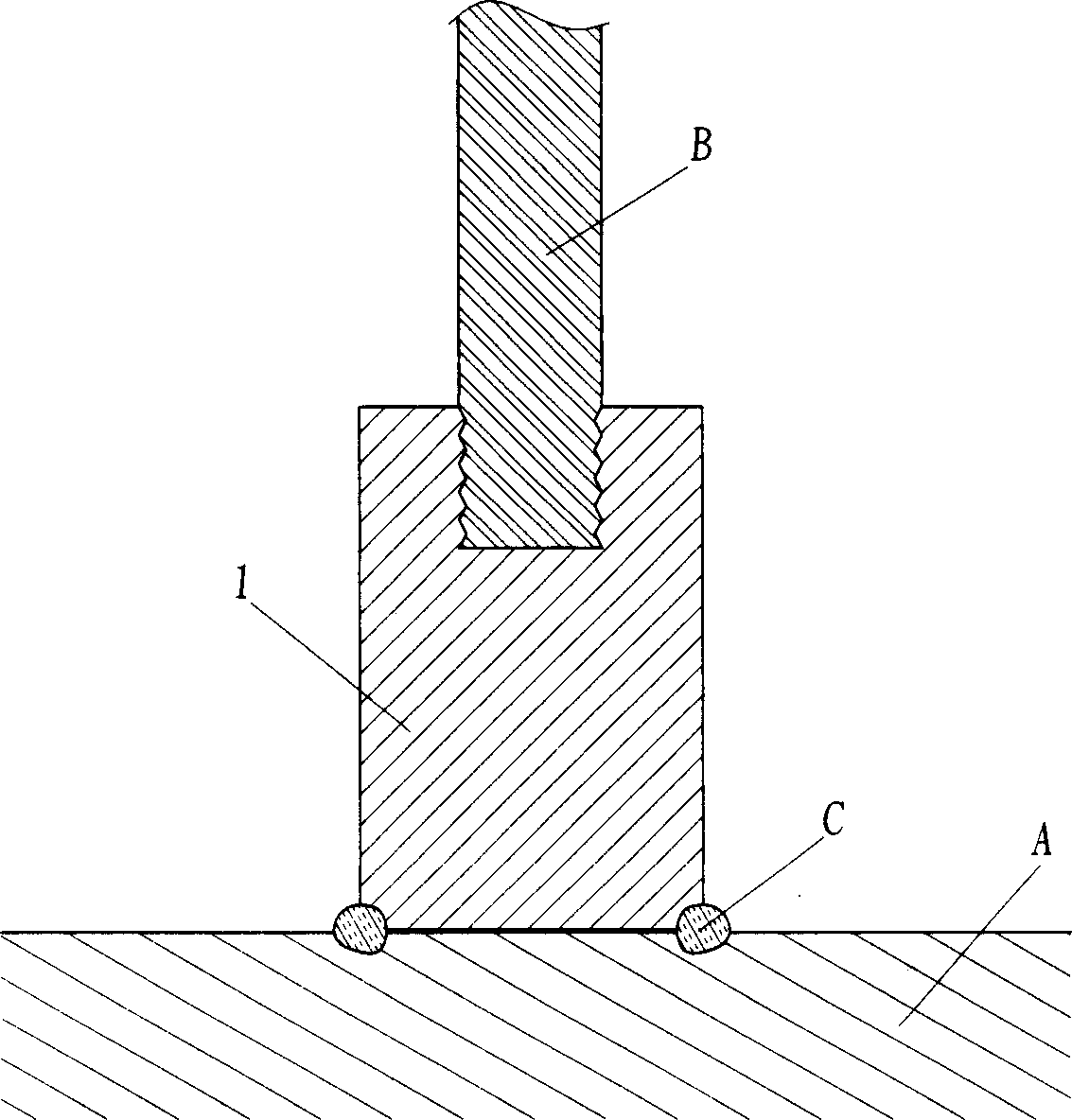
[0016] During construction, when the reinforcement connector 2 needs to be vertically welded to the steel structure A, the reinforcement connector 2 can be placed on the surface of the steel structure A, and then the protective ring 22 can be put on. Then, with the welding machine, the bottom of the steel bar connector 2 and the welding particles 21 are melted to form iron slurry by means of high-current instantaneous discharge. The iron slurry prod...


PUM


Abstract

The present ivnention discloses a steel bar splicing device implantation welding construction method, and is characterized by that the welding granules are implanted into the bottom end of the steel bar splicing device, the exterior of the steel bar splicing device is covered with a protection ring, on the protection body of protection ring several wave-formed air holes are set. When the construction is made, the steel bar splicing device is placed on the surface of steel skeleton structure, covered with protection ring, welded by implantation welding machine, so that the steel bar splicing device can be implanted into the steel skeleton structure. Said invention is applicable to welding of various steel bars splicing devices.

Description

Technical field: [0001] The invention relates to the welding of a metal reinforcing member, in particular to a welding method of a steel bar connector. Background technique: [0002] At present, the welding construction method of the steel bar connector used in general buildings, such as figure 1 , 2 As shown, it is mainly at the bottom of the steel bar adapter 1, using the method of manual electric welding, one by one to weld the steel bar adapter 1 on the surface of the general steel structure A, and then on the surface of the steel bar adapter 1 The steel bar B is screwed into the screw hole 10, so that the purpose of connecting the steel bar B can be achieved. However, in the above-mentioned construction method, because the bottom of the steel bar connector 1 is only partially fused with the welding spot C near the circumference, it does not completely cover it. The bottom area of ​​the entire steel bar coupler 1, therefore, only by a circle of solder joints C, its bon...

Claims


Application Information

Patent Timeline
Patent Type & Authority Applications(China)
IPC IPC(8): B23K31/02B23K33/00E04C5/18
Inventor 王台钦陈俊安
Owner 王台钦
Why Eureka
Try Eureka