
Knife sharpener capable of controlling angle

A knife sharpener and surface grinding technology, applied in the field of angle control, can solve problems such as inconvenient and clumsy devices

Inactive Publication Date: 2002-09-04
EDGECRAFT
View PDF4 Cites 14 Cited by
  • Summary
  • Abstract
  • Description
  • Claims
  • Application Information

AI Technical Summary

Problems solved by technology

A major disadvantage of using clamping devices or tool holders to control the sharpening angle is the bulky and inconvenient nature of these devices

Method used


Image

  • Knife sharpener capable of controlling angle
  • Knife sharpener capable of controlling angle
  • Knife sharpener capable of controlling angle

Examples


Embodiment Construction

[0022] Detailed description of the preferred embodiment

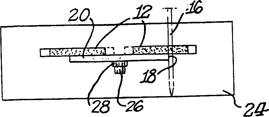
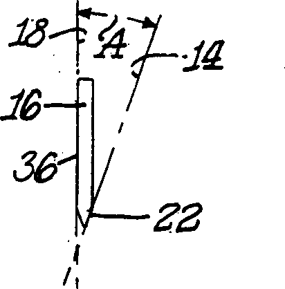
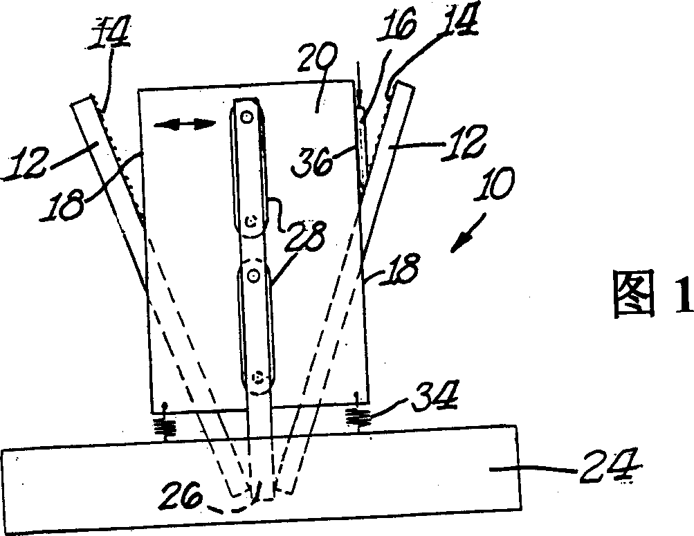
[0023] The above figures show a sharpener with a guide surface near the grinding surface so that the knife can rest on the guide surface and move on the grinding surface to sharpen the blade. In the different embodiments shown here, the linear guide surface can move along a direction perpendicular to the plane where it is located, and at the same time, the linear guide surface can remain parallel to its original plane at each position of the movement. In this way, the linear guide surface moves sideways without changing the angle. This movement is completely different from the following movement, that is, the linear guide surface of the knife surface is part of a heavy fixture or tool holder, and the movement of the linear guide surface is completely parallel to the plane of the contact point of the knife on the grinding surface.

[0024] Figures 1-3 show a manual sharpener 10 according to an embodiment of the present inven...


PUM


Abstract

A manual knife sharpener has an angle control structure. The structure includes a guide member with a guide surface forming an angle with the grinding surface of the grinding component. When the blade is inserted between the grinding surface and the guide surface, the blade pushes against the guide surface, causing the guide surface to move in a direction perpendicular to the guide surface, so that the movement is lateral movement in a plane, and the guide does not rotate. Or twisted. In this way, no matter how far the guide is moved, the angle between the guide surface and the grinding surface remains unchanged.

Description

[0001] Related application [0002] This application is based on the provisional application number 60 / 260980 and the application date of January 11, 2001. Background of the invention [0003] Many kinds of manual sharpeners have been used for a long time, but most of them are disappointing because they do not provide any precise device to control the sharpening angle. The importance of angle control for producing ultra-sharp blades has been recognized by, for example, U.S. Patent Nos. 5,390,431 and 4,627,194. [0004] In the other manual sharpeners described, the control of the sharpening angle is achieved by using a clamping device or a tool holder. The knife is fixed in the above mechanism and is physically restrained, so that when the clamping device or the tool holder is opposite When the grinding surface moves in a predetermined direction, the blade surface can be kept parallel to the grinding surface. One of the main disadvantages of using clamping devices or tool holders to...

Claims


Application Information

Patent Timeline
Patent Type & Authority Applications(China)
IPC IPC(8): B24B3/36B24D15/08
CPCB24D15/08
Inventor 老丹尼尔·D·弗里尔
Owner EDGECRAFT
Learn More