Gasifier fluid setscrew

A technology for adjusting screws and carburetors, used in carburetors, machines/engines, lift valves, etc., can solve the problems that the carburetor cannot be miniaturized, cannot maintain concentricity, and cannot supply low-speed mixed gas normally and uniformly. , to achieve the effect of precise and uniform adjustment

Inactive Publication Date: 2002-09-04
KEIHIN CORP
View PDF0 Cites 3 Cited by
  • Summary
  • Abstract
  • Description
  • Claims
  • Application Information

AI Technical Summary

Problems solved by technology

[0018] Since the above-mentioned correct concentricity cannot be maintained, in particular, a uniform annular gap cannot be formed between the conical needle valve portion 31 and the metering hole 42, resulting in the problem that the low-speed mixed gas cannot be supplied normally and uniformly.
[0019]

Method used


Image

  • Gasifier fluid setscrew
  • Gasifier fluid setscrew
  • Gasifier fluid setscrew

Examples


Embodiment Construction

[0026] Below, combine figure 1 One embodiment of the fluid adjustment screw of the present invention will be described.

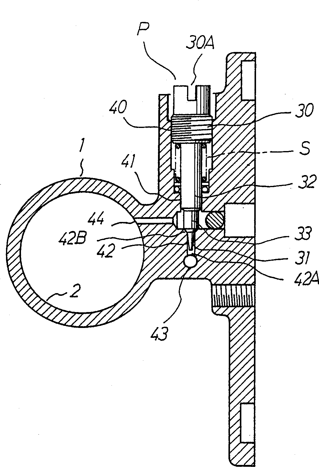
[0027] The fluid controller of this embodiment is the same vaporizer as the embodiment in the prior art, and the same structural parts are denoted by the same numbers.

[0028] 1 is the carburetor body which is installed inside and runs through the suction passage 2.

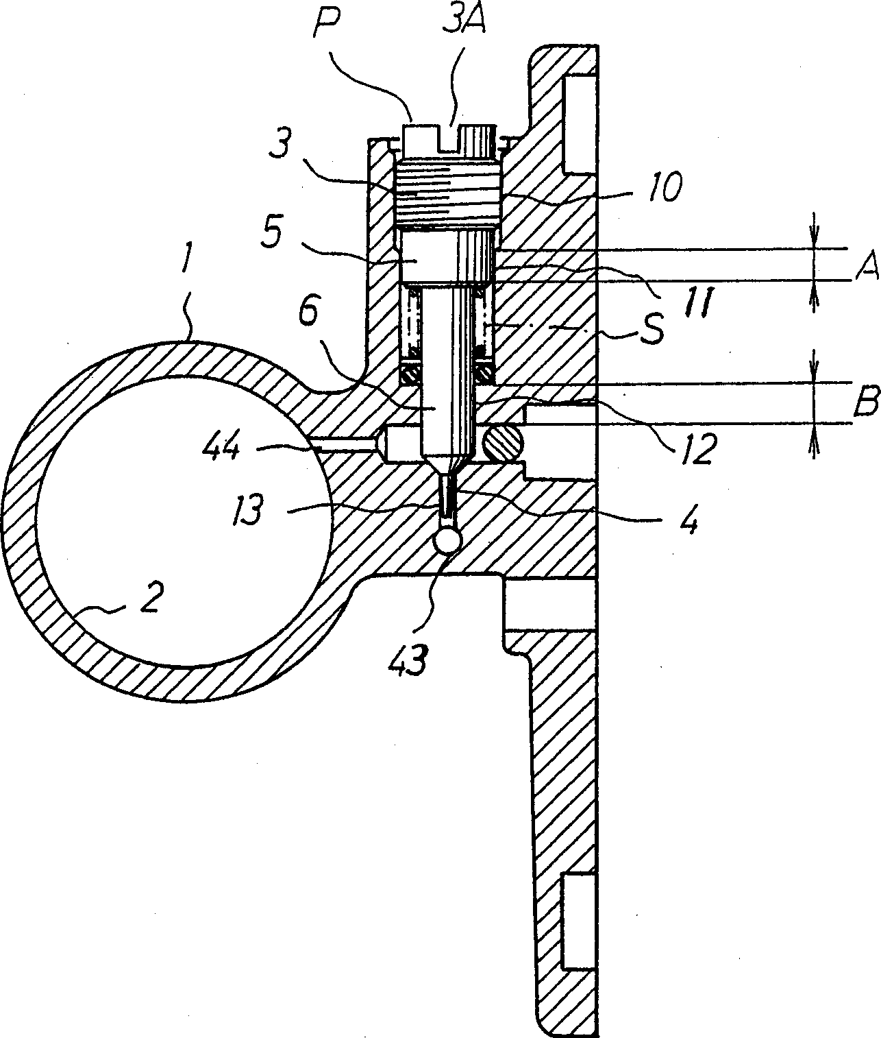
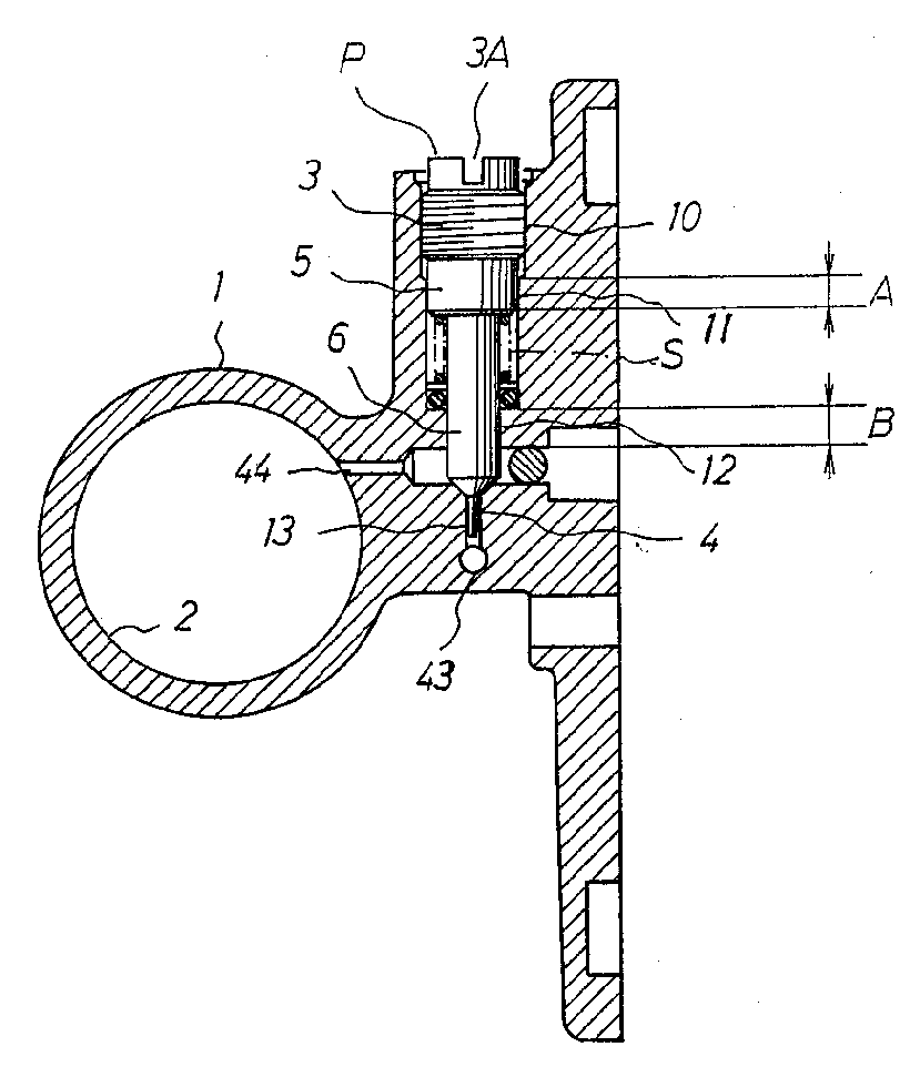
[0029] P is a fluid adjustment screw, which in this embodiment is the main control screw for adjusting the low-speed mixed gas volume.

[0030] Fluid adjustment screw P consists of the following parts:

[0031] 3 is a threaded part arranged at its rear end, and an adjustment groove 3A of inline shape, cross shape, etc. is set on its rear end surface;

[0032] 4 is a conical needle valve part arranged at its front end, and the threaded part 3 and the conical needle valve part 4 are connected in such a way that a large-diameter guide cylinder part 5 is sequentially arranged in succession to...


PUM


Abstract

The fluid adjusting screw of the present invention can form a uniform and accurate annular gap between the conical needle valve and the metering hole due to the improved concentric precision of the screw hole and the guided threaded hole, so that the flow rate of the fluid can be controlled with high precision. The measure is that a large-diameter guide cylinder part 5 and a small-diameter guide cylinder part 6 are arranged concentrically from the threaded part 3 of the fluid adjustment screw P toward the conical needle valve part 4, and concentrically inward at the outer end of the fluid controller 1. A connected female thread part 10, a large-diameter guide hole 11, a small-diameter guide hole 12 and a metering hole 13 are provided, the threaded part 3 of the fluid adjustment screw P is screwed into the female thread part 10, and the large-diameter guide cylinder part 5 Supported by the guide length (A) in the large-diameter guide hole 11, the small-diameter guide cylinder part 6 is supported by the guide length (B) in the small-diameter guide hole 12, and the conical needle valve part 4 is assembled in the metering hole 13 middle.

Description

technical field [0001] The present invention relates to a fluid adjustment screw arranged in a fluid controller for adjusting the fluid in the fluid controller, especially a fluid adjustment screw for a gasifier. Background technique [0002] Fluid adjustment screws for gasifiers in the prior art such as figure 2 shown, it is described below and the adjusting screw is referred to as the main control screw. [0003] 1 is the main body of the gasifier, and 2 is an air intake passage penetrating through the inside of the main body of the gasifier, and other elements constituting the gasifier are omitted in the figure. [0004] P is the main control screw as a fluid adjustment screw for adjusting the low-speed mixed gas volume, and the main control screw consists of the following parts: [0005] 30 is a threaded part arranged at its rear end, and a through groove 30A for rotating the main control screw P is arranged on its rear end surface; [0006] 31 is the conical needle v...

Claims


Application Information

Patent Timeline
IPC IPC(8): F02M3/10F02MF02M7/18F02M19/06F16K1/04
Inventor 秋山裕茂
Owner KEIHIN CORP
Why Eureka
Try Eureka