
Grain storage simulating device and method with precise temperature control

A technology of precise temperature control and simulation device, which is applied in fruit suspension devices, botanical equipment and methods, food preservation, etc. problems, to achieve the effect of convenient maintenance, uniform distribution, and efficient heat transfer

Pending Publication Date: 2020-04-07
HUNAN GRAIN GRP CO LTD +1
View PDF3 Cites 4 Cited by
  • Summary
  • Abstract
  • Description
  • Claims
  • Application Information

AI Technical Summary

Problems solved by technology

However, this device is a research on special conditions (condensation phenomenon), and it focuses on different fields. It is impossible to simulate the normal ambient temperature of the whole warehouse, and it is difficult to simulate the change mechanism of the whole grain pile under different temperature environments. At the same time, because the device uses Airflow cold source, airflow heat source temperature control, temperature control uniformity and accuracy are poor

Method used


Image

  • Grain storage simulating device and method with precise temperature control
  • Grain storage simulating device and method with precise temperature control
  • Grain storage simulating device and method with precise temperature control

Examples


Embodiment 1

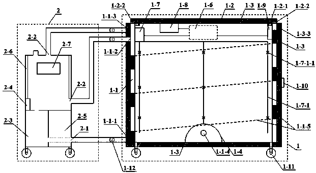
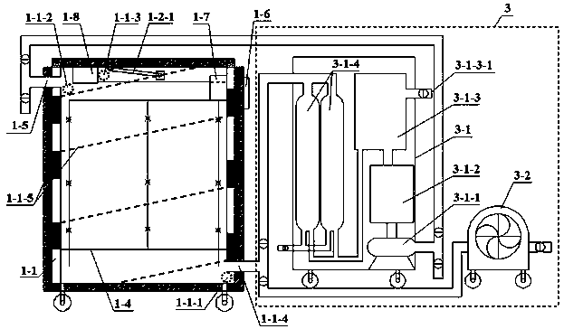
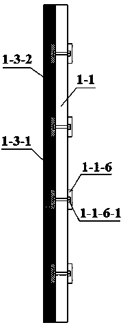
[0059] Such as Figure 1~5 As shown, the device includes a bin body 1, a liquid refrigerant temperature control unit 2 and an air control unit 3; the bin wall of the bin body 1 is provided with a 1 cm thick temperature control layer 1-1 (length 1.5m, width 1.0 m, height 1.3m), the top of the warehouse body 1 is provided with a movable top cover 1-2, and the bottom of the warehouse body 1, the temperature control layer 1-1 and the movable top cover 1-2 are provided with an insulation layer 1-3 ; The outer side of the lower end of the temperature control layer 1-1 is provided with a water inlet 1-1-1, which is connected with the water outlet 2-1 of the liquid refrigerant temperature control unit 2; The water outlet 1-1-2 and the overflow outlet 1-1-3 are respectively connected to the water inlet 2-2 of the liquid refrigerant temperature control unit 2; the inside center of the bottom of the warehouse body 1 is provided with an above-ground cage 1-4 (length 1m , 0.4m in width an...

Embodiment 2

[0066] The difference between the embodiment of the present invention and embodiment 1 is only: as Figure 6 As shown, the diversion mechanism 1-1-5 is parallel to the bottom surface of the warehouse body 1, and the diversion mechanism 1-1-5 divides the temperature control layer 1-1 into 3 layers, and is provided with a water inlet 1-1 -1. In the temperature control layer 1-1 on the side of the water outlet 1-1-2 and the overflow 1-1-3, there is also a continuous and longitudinal "S"-shaped flow guide mechanism 1-1-5 , the arc-shaped outer sides of the uppermost and lower ends of the "S"-shaped flow guide mechanism 1-1-5 are respectively facing the water outlet 1-1-2 and the water inlet 1-1-1, and the horizontal flow guide mechanism 1-1- 5 is connected to the outside of each arc, and the horizontal diversion mechanism 1-1-5 is 20cm away from the inner side of each arc; the upper and lower arcs of the "S"-shaped diversion mechanism 1-1-5 are tangent, and the arc The radius is ...

Embodiment 3

[0069] The difference between the embodiment of the present invention and embodiment 1 is only: as Figure 7 As shown, in the temperature control layer 1-1 on the side of the water inlet 1-1-1, the water outlet 1-1-2 and the overflow 1-1-3, the flow guide mechanism 1-1 of each adjacent layer -5 are parallel to each other, and form 23.4° with the bottom surface of the warehouse body 1, the vertical distance between the diversion mechanisms 1-1-5 of adjacent layers is equal and 39.8cm, and the temperature control layer 1-1 on the other three sides The inside extends parallel to the bottom surface of the warehouse body 1 . The rest are the same as embodiment 1.

[0070] After testing, the device of the present invention can regulate the temperature of the warehouse wall and precisely control the temperature of the warehouse body, and the design in terms of heat preservation, temperature control, and uniform temperature makes the temperature control accuracy reach ±0.1°C.

[007...


PUM


Abstract

The invention discloses a grain storage simulating device and method with precise temperature control. The device comprises a bin, a liquid refrigerant temperature control unit and an air control unit; a temperature control layer is arranged on a bin wall of the bin, a movable roof is arranged on the top of the bin, and thermal insulation layers are arranged on the bottom of the bin, on the temperature control layer of the bin and in an interlayer of the movable roof; a first water inlet is formed in the outer side of the lower end of the temperature control layer, and is connected with a first water outlet of the liquid refrigerant temperature control unit; a second water outlet and an overflow opening are formed in the outer side of the upper end of the temperature control layer, and areconnected with a second water inlet of the liquid refrigerant temperature control unit; an overground cage is arranged at a center of the inner side of the bottom of the bin, and an air inlet, whichis formed in the bin wall and runs through the overground cage, is connected with a nitrogen production device and a ventilation device; an air outlet formed in the upper end of the bin is connected with the nitrogen production device; a grain storage situation measurement and control machine, a nitrogen concentration detection instrument and an electronic hygrothermograph which are connected witha measurement and control panel are arranged on the upper portion of the interior of the bin; and temperature measurement cables are connected with the grain storage situation measurement and controlmachine. The grain storage simulating method with precise temperature control is further disclosed. The device and method can precisely control the temperature, and are high in precision.

Description

technical field [0001] The invention relates to a grain storage simulation device and method, in particular to a grain storage simulation device and method for precise temperature control. Background technique [0002] "The people are the foundation of the country, and the valley is the life of the people." Food is the main resource for national survival and national development, and food security is an important basis for national security. Therefore, food reserves are of great significance to ensure the "long-term stability" of my country's food security. my country has a large amount of grain reserves and a long storage period. Scientifically and reasonably reducing quality loss and storage energy consumption have always been the focus of my country's grain industry. influence is particularly important. In the existing research technology, there are many inconvenient factors such as uncontrollable environmental conditions, many manual intervention measures, and high test...

Claims


Application Information

Patent Timeline
Patent Type & Authority Applications(China)
IPC IPC(8): A01F25/14A01F25/22A23B9/10A23B9/20
CPCA01F25/14A01F25/22A23B9/10A23B9/20
Inventor 周涛黄天柱张兵陈渠玲刘博张源泉裴健儒甘平洋朱凤霞陈昌勇徐晓闻莫韩御毛青秀刘明何攀
Owner HUNAN GRAIN GRP CO LTD
Learn More