Three-phase induction motor and its speed regulating method

A technology of induction motor and speed regulation method, which is applied to asynchronous induction motors, electrical components, electromechanical devices, etc., can solve problems such as cost increase, harmonic pollution, influence of three-phase induction motors, etc., and achieves low cost, high reliability, The effect of increasing the number of speed control stages

Inactive Publication Date: 2002-09-04
SOUTH CHINA UNIV OF TECH
View PDF0 Cites 3 Cited by
  • Summary
  • Abstract
  • Description
  • Claims
  • Application Information

AI Technical Summary

Problems solved by technology

Voltage regulation and speed regulation require additional voltage regulation devices (such as transformers, saturated reactors, etc.), which increase the cost; if

Method used


Image

  • Three-phase induction motor and its speed regulating method
  • Three-phase induction motor and its speed regulating method
  • Three-phase induction motor and its speed regulating method

Examples


Embodiment 1

[0054] Embodiment 1 t Embodiment when it is an even number (take the stator 36-slot 4-pole three-phase induction motor as an example)

[0055] 1. The structure, phase belt, connection method and number of outgoing wires of the stator winding

[0056] (1) The structure, phase belt, connection method and number of outgoing wires of the phase-fixed winding

[0057] The phase-fixed winding adopts a double-layer stacked winding structure, and the pitch is y 1= 8 slot distances, 60° phase belt, triangle connection (i.e. Δ connection), one outgoing line for each phase, a total of three outgoing lines. The specific design of the phasing winding is the same as that of the ordinary single-speed three-phase induction motor stator winding design, which is omitted here.

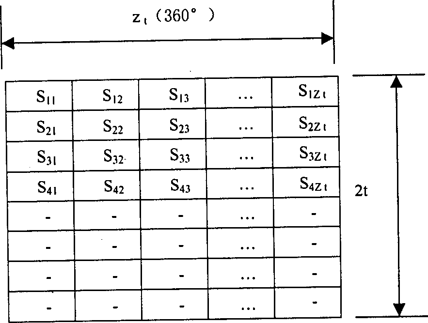
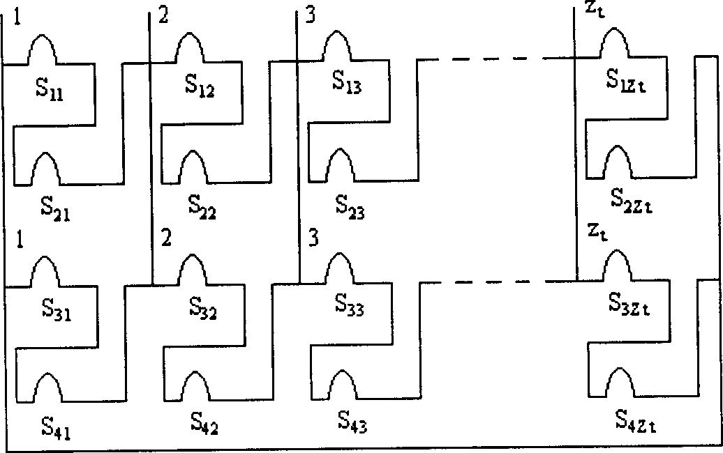
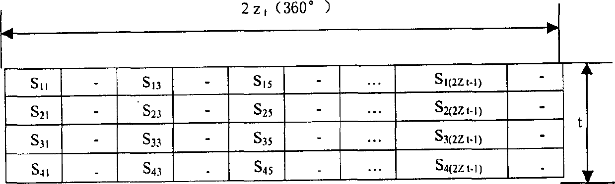
[0058] (2) The structure, phase belt, connection method and number of outgoing wires of the moving phase winding

[0059] The moving phase winding adopts a double-layer stacked winding structure, and the pitch is y 1...

Embodiment 2

[0068] Embodiment two z t Embodiment when it is an odd number (take the stator 36-slot 8-pole three-phase induction motor as an example)

[0069] 1. The structure, phase belt, connection method and number of outgoing wires of the stator winding

[0070] (1) The structure, phase belt, connection method and number of outgoing wires of the phase-fixed winding

[0071] The phase-fixed winding adopts a double-layer stacked winding structure, and the pitch is y 1 = 4 slot distances, 60° phase belt, triangle connection (i.e. Δ connection), one outgoing line for each phase, a total of three outgoing lines. The specific design of the phasing winding is the same as that of the ordinary single-speed three-phase induction motor stator winding design, which is omitted here.

[0072] (2) The structure, phase belt, connection method and number of outgoing wires of the moving phase winding

[0073] The moving phase winding adopts a double-layer stacked winding structure, and the pitch is ...


PUM


Abstract

The present invention is a three phase induction motor and its speed regulating method which is called modified line phase shift speed regulating method. The three phase induction motor consists of astator and a rotor, of which there is a fixing phase winding with fixed phase shaft and a moving phase winding with movable phase shaft on stator. Each of these two winding will produce a rotary magnetic field and these two rotary magnetic fields having space phase difference will produce two induction potentials having time phase difference accordingly. To move phase shaft of woving phase winding by changing outlet line of moving phase winding to change space phase difference between two rotary magnetic fields and further to change time phase difference between two induction potentials in rotor guide strip, hence the current and composite induction potential in rotor guide strip will be changed and accordingly the rotor rotating speed and electromagnetic torque of three phase induction motor will be change too. The speed can be regulated in multistaze with no harmonic wave pollution.

Description

(1) Technical field [0001] The invention relates to the technical field of electric drive (transmission) with multi-stage speed regulation, in particular to a three-phase induction motor and a speed regulation method thereof. (2) Background technology [0002] At present, three-phase induction motors mainly have the following five speed regulation methods: frequency conversion speed regulation, pole-changing speed regulation, cascade speed regulation, electromagnetic slip clutch speed regulation and voltage regulation. Although frequency conversion speed regulation has good speed regulation smoothness, it brings harmonic pollution that cannot be ignored to the power grid. This pollution has become a public hazard. At the same time, harmonics also cause increased losses to the three-phase induction motor itself Efficiency reduction, power factor reduction and other adverse effects. Although the pole-changing speed regulation is low in cost and has no harmonic pollution, its ...

Claims


Application Information

Patent Timeline
IPC IPC(8): H02K3/28H02K17/12
Inventor 程小华
Owner SOUTH CHINA UNIV OF TECH
Why Eureka
Try Eureka