Portable radio unit
A radio unit, portable technology, applied in the direction of wireless communication, electrical components, slender active unit end feed, etc., can solve the problems of complicated mechanism, lower antenna efficiency, inconvenient feeder setting, etc.
- Summary
- Abstract
- Description
- Claims
- Application Information
AI Technical Summary
Problems solved by technology
Method used
Image
Examples
Embodiment approach 1
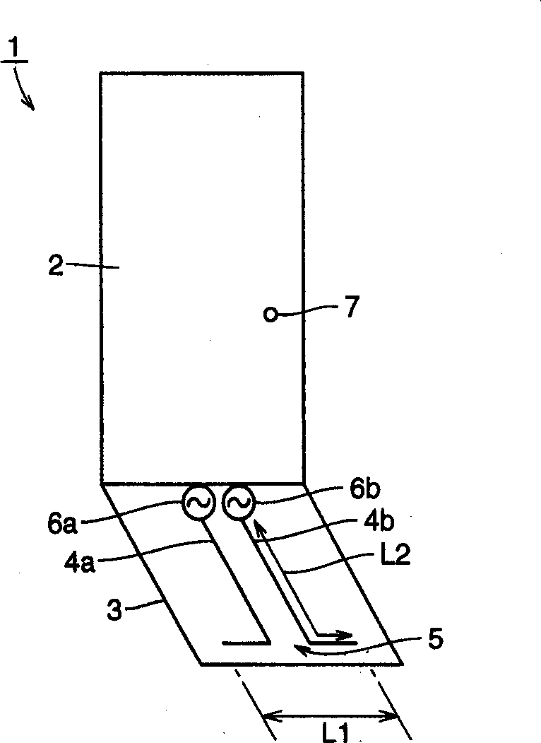
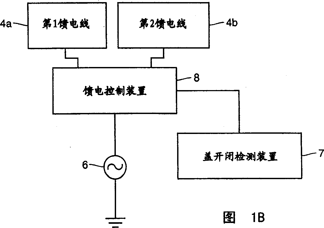
[0038] Such as Figure 1A As shown, the portable radio unit 1 has a casing 2 (ground conductor), a cover (flip cover) 3 that can be opened and closed freely, a dipole antenna 5, a first and a second feeder 4a, 4b, an RF (Radio Frequency) power supply 1 and the second power supply 6a, 6b and the cover opening and closing detection device 7.
[0039] The cover 3 is openably and closably attached to the case 2, is made of, for example, a dielectric material such as an organic polymer, and has a dipole antenna 5 inside. The dipole antenna 5 has a length L1 of one-half wavelength (λ / 2), and extends in a direction perpendicular to the long direction of the housing 2 . As a result, when the housing 2 is tilted to make a call, the polarized wave component perpendicular to the ground increases, and the consistency with the base station of the vertically polarized wave becomes better.
[0040] The first and second feeding lines 4a, 4b and the first and second power sources 6a, 6b oper...
Embodiment approach 2
[0049] Next, use Figure 3A and 3B Embodiment 2 of the present invention and its improvements will be described.
[0050] Such as Figure 3A As shown, in Embodiment 2 of the present invention, the tip of the dipole antenna 5 is bent. Thereby, the physical length of the dipole antenna 5 can be shortened, and the dipole antenna 5 can be made more compact. other structures and Figure 1A The same applies to the first embodiment shown.
[0051] In addition, as shown in FIG. 3 , the top end of the dipole antenna 5 can also be bent into a serpentine shape. In this case also, the same effect can be obtained.
Embodiment approach 3
[0053] Next, use Figure 4A and Figure 4B Embodiment 3 of the present invention will be described. Such as Figure 4A As shown, in Embodiment 3, the coaxial line 9 is used as the feeder. The coaxial line 9 has an outer conductor 9a and an inner conductor 9b, and the outer conductor 9a is short-circuited to the case. That is, the outer conductor 9a is grounded.
[0054] Coaxial lines 9, such as Figure 4B As shown, it is arranged to be spaced from the casing, and one end of the external conductor 9a is short-circuited with the casing 2 at the short-circuit point 11. In addition, if Figure 4A and Figure 4B As shown, the interval L3 between the feeding point 10 of the outer conductor 9a and the above-mentioned short-circuit point 11 is approximately λ / 4. Thereby, since the estimated impedance from the power source 6 a to the short-circuit point 11 becomes infinite, it is possible to suppress the influence of the short-circuit point 11 on the impedance of the feeding po...
PUM
 Abstract
Description
Claims
Application Information
 - R&D
- Intellectual Property
- Life Sciences
- Materials
- Tech Scout
- Unparalleled Data Quality
- Higher Quality Content
- 60% Fewer Hallucinations
Browse by: Latest US Patents, China's latest patents, Technical Efficacy Thesaurus, Application Domain, Technology Topic, Popular Technical Reports.
© 2025 PatSnap. All rights reserved.Legal|Privacy policy|Modern Slavery Act Transparency Statement|Sitemap|About US| Contact US: help@patsnap.com


