Eureka AIR delivers breakthrough ideas for toughest innovation challenges, trusted by R&D personnel around the world.

Variable voltage compensation

A technology of voltage and compensation speed, which is applied in the field of operation mode of switched reluctance drives, and can solve problems such as difficulty in reading control rule tables, large storage space, etc.

Inactive Publication Date: 2002-10-16
NIDEC SR DRIVES
View PDF1 Cites 3 Cited by
  • Summary
  • Abstract
  • Description
  • Claims
  • Application Information

AI Technical Summary

Problems solved by technology

Although these changes can be partially improved by characterizing the system at different voltage values, this method is time-consuming and requires a considerable storage space in the control system, making it more difficult to read the control rule table. Specific voltage for precise compensation

Method used


Image

  • Variable voltage compensation
  • Variable voltage compensation
  • Variable voltage compensation

Examples


Embodiment Construction

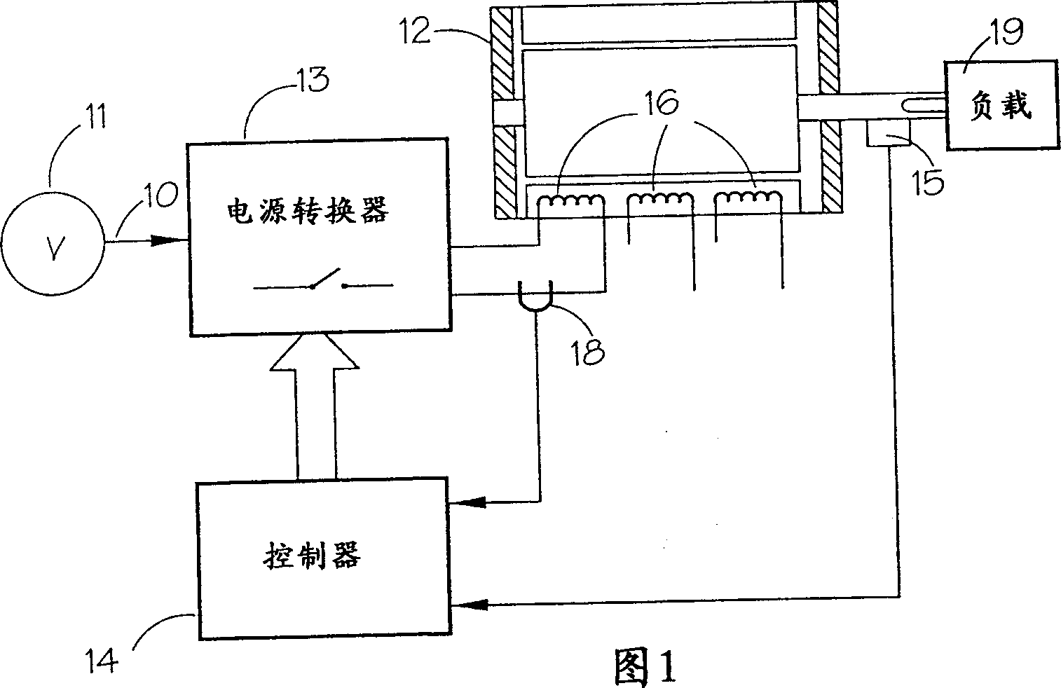
[0026] attached Figure 5 The device is used to implement an improved method of voltage compensation. A switched reluctance motor 12 is shown for driving a load 19 . The voltage source 11 supplies power to the driver, which can be a DC power supply or a rectified AC power supply. The DC link is represented by a connection 10 and is switched via a switching device 13 to a phase winding 16 of a switched reluctance motor 12 on which a controller 14 determines the firing angle. Also included is a rotor position sensor 15 (RPT) responsive to an element that rotates with the rotor of switched reluctance motor 12 for generating a rotor position sensor output signal representative of rotor position. As can be seen, position information can be obtained by various methods, such as using software algorithms that estimate this information from the current, voltage and / or inductance of the motor. The current in the phase windings is measured by a conventional type current sensor 18 and ...


PUM


Abstract

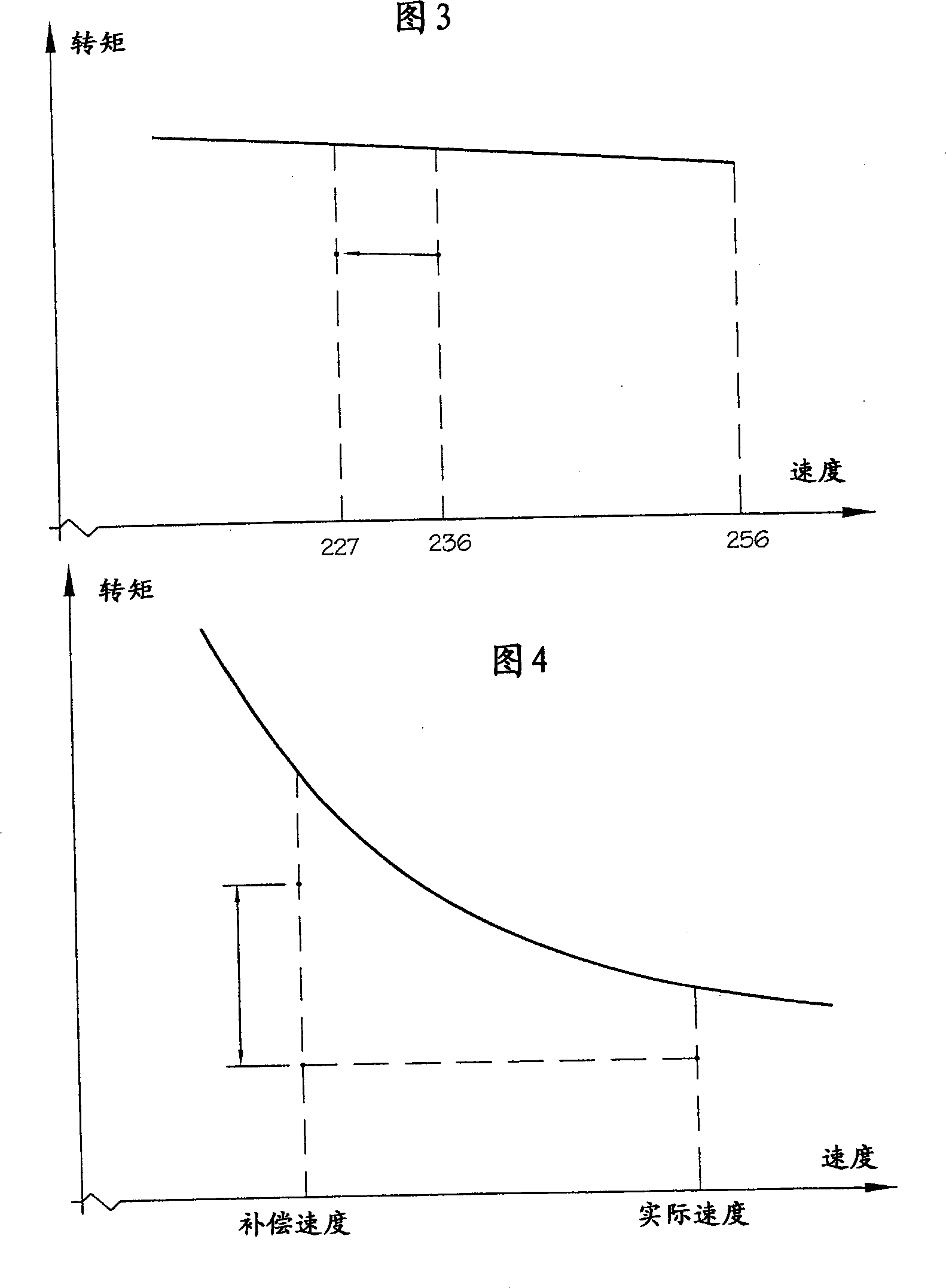
The present invention relates to variable voltage compensation in which a switched reluctance driver is powered by a voltage source that is different from the voltage determined for the driver control rules. The control system compensates for these differences by simultaneously correcting the speed and torque values, which are used to determine the correct firing angle for the load required to drive. The system can operate in environments where a wide voltage variation range occurs and is independent of the shape of the drive's torque / speed curve.

Description

technical field [0001] The present invention generally relates to methods and apparatus for compensating DC link voltage deviations in electric drive systems. In particular, the invention relates to the mode of operation of a switched reluctance drive capable of periodically reading a value corresponding to a certain DC link voltage, adjusting a speed indicating signal for compensating voltage changes that occur. The compensated speed signal is sent to a controller where energy changes in the switched reluctance drive coil are compensated for. Background technique [0002] Theoretical aspects of the design and operation of switched reluctance motors are well known and described, for example, in the article "Characteristics, Design and Applications of Switched Reluctance Motors and Drives" by Stephenson and Blake, June 21, 1993 -On the 24th, it was made public at the PCIM 93 Annual Conference and Exhibition held in Nuremberg, Germany, and is quoted here; as a reference. Th...

Claims


Application Information

Patent Timeline
Patent Type & Authority Applications(China)
IPC IPC(8): H02P25/08
CPCH02P25/08Y10S388/902
Inventor 米切尔·L·麦克莱兰德乔纳森·R·奎恩
Owner NIDEC SR DRIVES
Why Eureka
Eureka Blog
Learn More