
Passively-driven safe needle

A passively driven, safe needle technology, used in needles, medical science, surgery, etc., to solve problems such as pain

Inactive Publication Date: 2002-12-11
BECTON DICKINSON & CO
View PDF1 Cites 15 Cited by
  • Summary
  • Abstract
  • Description
  • Claims
  • Application Information

AI Technical Summary

Problems solved by technology

Accidental needlesticks with sterile needles are painful and can leave open wounds that become infected

Method used


Image

  • Passively-driven safe needle
  • Passively-driven safe needle
  • Passively-driven safe needle

Examples


Embodiment Construction

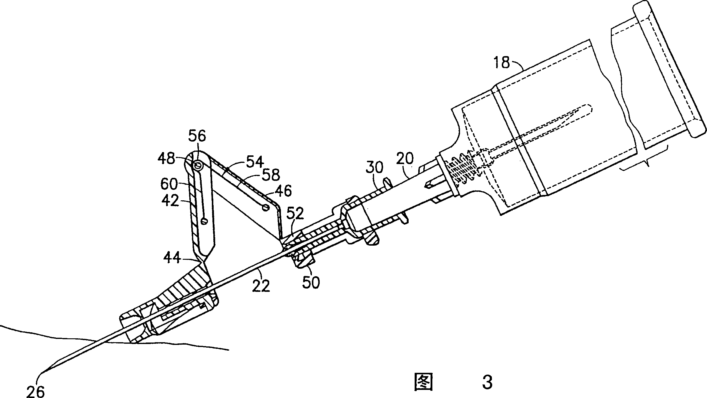
[0024] exist figure 1 The passively actuated safety needle of the present invention is generally indicated by reference numeral 10 in . Passively actuated safety needle assembly 10 includes a needle assembly 12 , a safety cap 14 and a shield assembly 16 . The safety needle assembly 10 may be mounted to a medical implement, such as a syringe or a needle holder. E.g, figure 2 A passively actuated safety needle assembly 10 is shown mounted to a needle holder 18 for use with an evacuated blood collection tube to collect a patient's blood sample. Needle holder 18 may be of prior art design and is formed from a Luer sleeve 20 having a channel therethrough.

[0025] Needle assembly 12 includes a cannula 22 having a proximal end 24 , a distal end 26 beveled to a sharp point, and a lumen 28 extending between ends 24 and 26 . Needle assembly 12 also includes a plastic socket 30 . The proximal end 24 of the needle cannula 22 is secured into the socket 30 by an adhesive 32 . Recept...


PUM


Abstract

A passively driven safety needle assembly includes a needle assembly, a shielding assembly and a safety cap. The needle assembly includes a socket and a needle tube protruding from the socket. The shield assembly includes a safety sheath installed to slide along the needle tube. The shield assembly also includes a plurality of arms that are hinged to each other to allow the safety sheath to slide along the needle tube from a proximal position to a distal position shielding the tip of the needle tube. A spring is secured to the shield assembly and uses it to drive the safety sheath from its proximal position to its distal position. The safety helmet mounts over the shield assembly and retains the shield assembly in the proximal position. Hold the arm during use of the safety needle. Upon releasing the arm, the spring automatically drives the sheath distally without any user actuation.

Description

technical field [0001] The present invention relates to a passively actuated safety needle assembly for preventing accidental needle sticks. Background technique [0002] Many medical procedures require the use of a sharp metal needle to obtain fluid samples from a patient or to infuse a patient. The pointed metal cannula must be handled carefully to avoid accidental sticks from the cannula tip. Accidental needlesticks with sterile needles are painful and may leave open wounds that become infected. Accidental sticks from used syringes can transmit disease. [0003] Safety boots are widely used in the healthcare industry to eliminate or reduce the risk of accidental needle sticks. The safety sheath can take a variety of forms, including a sheath that is inserted along the needle barrel from a proximal location to a distal location. When the sheath is in the proximal position, the distal end of the needle cannula is exposed for use. However, when the sheath is in the dist...

Claims


Application Information

Patent Timeline
IPC IPC(8): A61B5/15A61M5/32
CPCA61M5/3202A61M5/3257A61M5/3275A61M2005/325Y10S128/919A61B5/15003A61B5/150259A61B5/150389A61B5/150503A61B5/150572A61B5/150648A61B5/150717A61B5/150732A61B5/154
Inventor W·E·小沃德
Owner BECTON DICKINSON & CO
Learn More