Multi-layer magnetic engaged wheel and magnetic gearing device

A technology of magnetic transmission and meshing gear, which is applied in transmission devices, electromechanical devices, permanent magnet clutches/brakes, etc. It can solve the problems of inability to apply high-power transmission and small maximum meshing force, and achieve large meshing force and low noise , the effect of high speed

Inactive Publication Date: 2002-12-18
沈源源
View PDF3 Cites 20 Cited by
  • Summary
  • Abstract
  • Description
  • Claims
  • Application Information

AI Technical Summary

Problems solved by technology

It can be seen from the above that the common disadvantage of the above patents is that the maximum meshing force is too small to be applied to the transmission of relatively large power

Method used


Image

  • Multi-layer magnetic engaged wheel and magnetic gearing device
  • Multi-layer magnetic engaged wheel and magnetic gearing device
  • Multi-layer magnetic engaged wheel and magnetic gearing device

Examples


Embodiment Construction

[0080] Preferred embodiments of the invention are described below with the aid of the drawings.

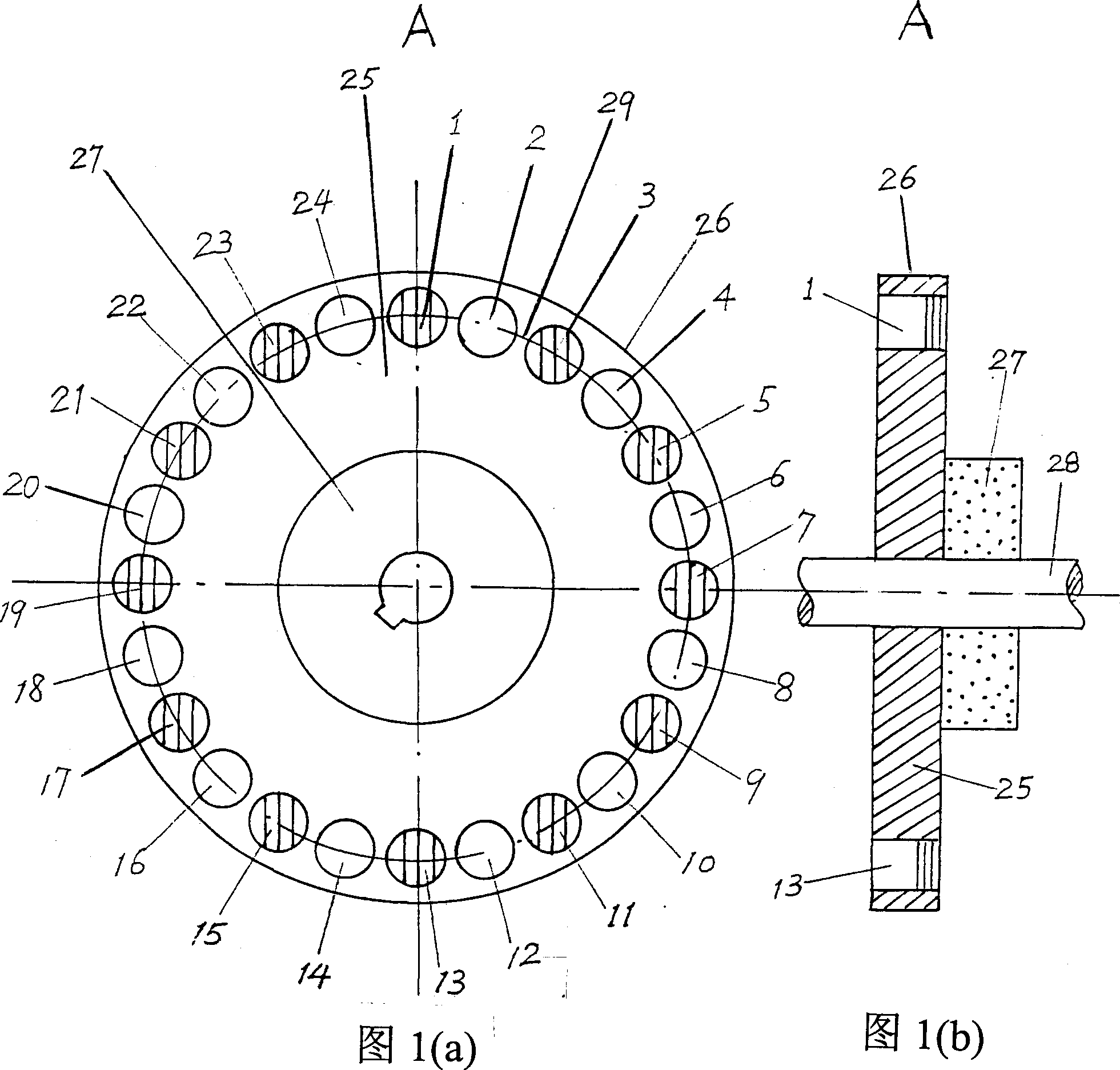
[0081] Fig. 1 (a) and 1 (b) are according to the structural diagram of multilayer planar magnetic gear A of preferred embodiment of the present invention, wherein Fig. 1 (a) is its front view, and Fig. 1 (b) is multilayer Axial sectional view of the plane magnetic mesh wheel, for the sake of simplification, only one layer is drawn in Fig. 1(b). As shown in Figure 1 (b), this layer of planar magnetic gears includes a magnetic wheel (magnetic wheels) 26, a spacer (Spacer) 27 and a shaft 28, and the shaft 28 runs through the center of the magnetic wheel 26 and through the spacer 27, and the magnetic disc wheel 26 and spacer 27 are fixed on the rotating shaft 28 and the planes of both are perpendicular to the rotating shaft 28. As shown in Fig. 1 (a), the disk wheel 26 is composed of a rotatable flat disc-shaped base 25 and magnets 1-24 arranged on the base 25, and the magnets 1-24 a...


PUM


Abstract

The present invention provides a kind of multilayer planar magnetic engaged wheel and multilayer spherical magnetic engaged wheel and magnetic transmission equipment adopting this magnetic engaged wheel. Said multilayer magnetic engaged wheel is formed from several rotatable bases, several spacing pieces rotatable together with bases, magnetic bodies distributed on the bases and rotating shaft. Its whose magnetic engaged wheel is made up by alternatively and axially coinciding bases with magnetic bodies and spacing pieces togehter. The magnetic bodies are uniformly-spaced and arranged on the graduated cycle of base and magnetic shaft directions are alternatively arranged, in the engaged position of two engaged wheels any magnetic body or magnetic pole of one magnetic engaged wheel is being in magnetic potential well formed from several magnetic bodies or magnetic poles of another magnetic engaged wheel.

Description

technical field [0001] The present invention relates to a transmission part and device, in particular to a magnetic meshing wheel and a magnetic speed-changing transmission device which uses mutual attraction and repulsion between magnets instead of mechanical force as the meshing force. Background technique [0002] Mechanical gears are currently the most widely used transmission devices with the best performance. However, the gears are worn and need to be lubricated, and have no overload protection function. The maximum linear speed cannot exceed 250m / s, and the noise is very loud at high speeds, and the manufacturing requirements are also high. [0003] Compared with mechanical gears, magnetic gears have a series of advantages such as high mechanical efficiency, no contact, low noise and no wear. British patent EP1069671 published on January 17, 2001 and US patent 5569967 published on October 29, 1996 disclose two magnetic gear structures. Among them, EP1069671 disclose...

Claims


Application Information

Patent Timeline
Patent Type & Authority Applications(China)
IPC IPC(8): F16H49/00H02K49/10
CPCF16H49/005H02K49/102
Inventor 魏乐汉
Owner 沈源源
Why Eureka
Try Eureka