Date recording device, controlling device for data recording device and data recording method

A technology for data recording and control devices, which is applied in the field of recording media and data recording devices, and can solve problems such as inability to restart recording properly, errors in pit patterns, and inability to correctly find data, etc.

Inactive Publication Date: 2003-01-01
PANASONIC CORP
View PDF2 Cites 1 Cited by
  • Summary
  • Abstract
  • Description
  • Claims
  • Application Information

AI Technical Summary

Problems solved by technology

[0008] However, the above-mentioned device for finding the recording position by counting PLL clocks also has the following problems: when reproducing the recorded data, especially the synchronous pattern, if there is a scratch on the optical disc or the pit pattern is unstable due to vibration etc. will error out without properly restarting the recording
However, if a playback error occurs at the place where the sync pattern is recorded when the interrupted recording is restarted, the position of the last recorded data before the interruption of the recording cannot be correctly found, and seam-free operation cannot be performed. continuous record of

Method used


Image

  • Date recording device, controlling device for data recording device and data recording method
  • Date recording device, controlling device for data recording device and data recording method
  • Date recording device, controlling device for data recording device and data recording method

Examples


Embodiment Construction

[0035] Hereinafter, embodiments of the present invention will be described with reference to the drawings.

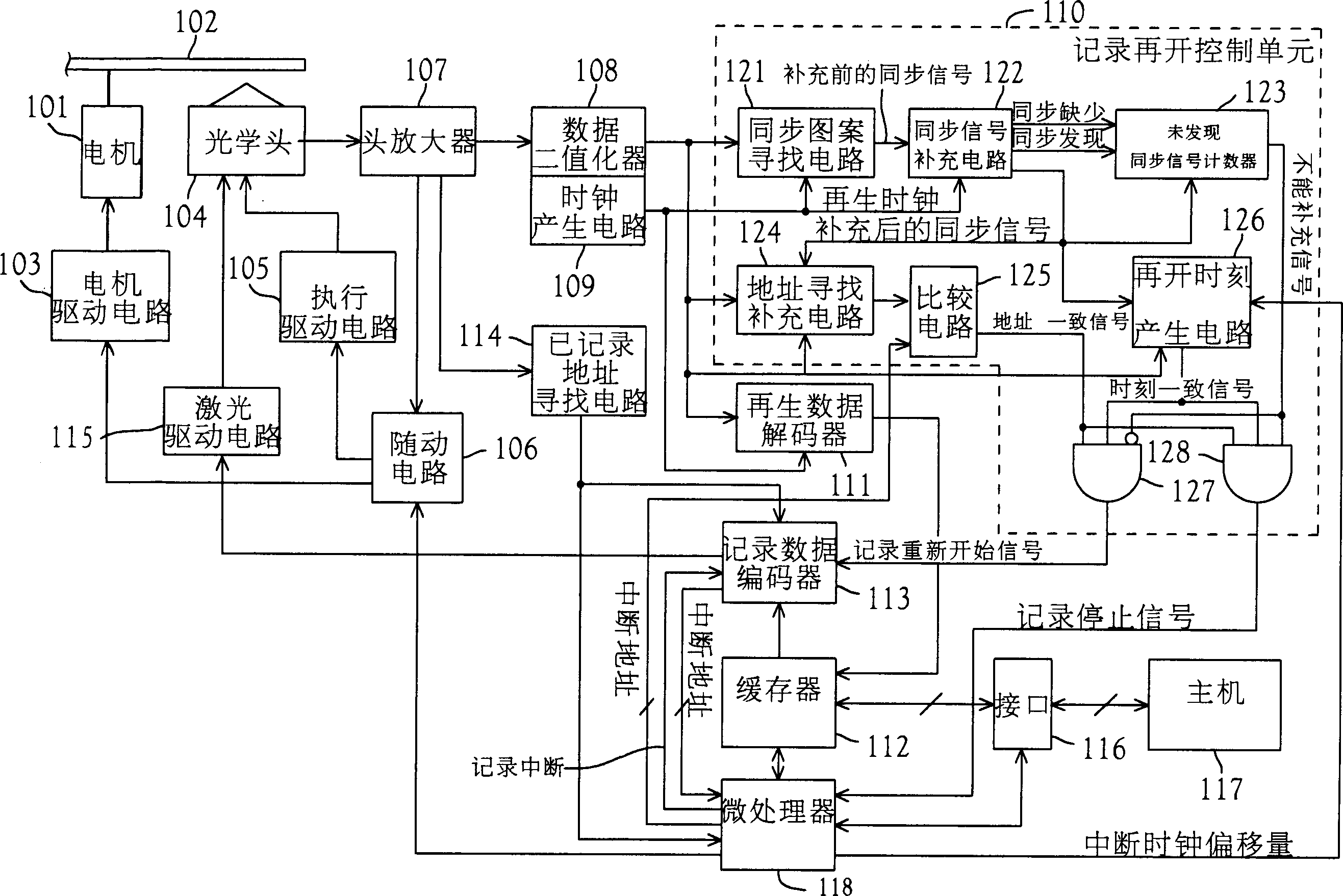
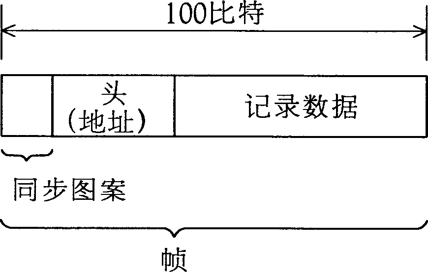
[0036] figure 1 It is a block diagram showing the overall configuration of the data recording device according to Embodiment 1 of the present invention. figure 2 The original format of the recorded frame is shown. It should be mentioned that, for the sake of convenience, the case where a complete address is followed by the synchronization pattern shown in the figure is taken as an example for description.

[0037] exist figure 1 Among them, the rotary motor 101 drives the optical disc 102 to rotate; the motor drive circuit 103 drives the above-mentioned rotary motor 101; Light and regenerate the data wherein; Execute drive circuit 105 to drive above-mentioned optical head 104; Follow-up circuit 106 controls the rotating speed of rotating motor 101, the focusing of optical head 104 and track tracking etc.; Head amplifier 107 amplifies the RF signal output from opti...


PUM


Abstract

A data recording device, in the case where a data recording operation is suspended, even when a synchronization pattern cannot be detected due to a scratch of an optical disk or the like, a position where the last data is recorded is precisely detected so as to resume the recording operation without causing a joint. For this purpose, in resuming the suspended recording operation in the data recording device of this invention, reproducing pattern data corresponding to a pit pattern having been recorded in the optical disk is first reproduced. A synchronization pattern detection circuit detects a synchronization pattern and outputs a pre-complementation synchronization signal. A synchronization signal complementation circuit detects presence of a synchronization signal (synchronization signal pulse) and outputs a detection/loss signal to a synchronization signal non-detection counter. Also, when the synchronization signal is lost, the synchronization signal complementation circuit complements the synchronization signal and outputs a post-complementation synchronization signal to an address detection/complementation circuit and the like. The synchronization signal non-detection counter outputs a non-complementation signal when synchronization signals are continuously lost, so as to stop the resumption of the recording operation.

Description

technical field [0001] The present invention relates to a technology related to data recording devices for recording and reproducing data on recording media such as optical discs, specifically CD-R (Compact Disc Recordable), CD-RW (Compact Disc Rewritable), etc. . Background technique [0002] When recording data to an optical disc such as CD-R, CD-RW, etc., it is usually called disc at once, track at once, etc., in one recording operation. Complete the recording of the entire track, the entire disc. Like this, once the data recording fails, or the disc will be broken, or the data that has been recorded will disappear. Buffer underrun error (buffer underrun error) and the like are the main reasons for the above record failure phenomenon. When the transmission speed of the recording data transmitted from the host computer is slower than the recording speed of the optical disk device, the buffer area for temporarily storing the recording data becomes empty and the recording...

Claims


Application Information

Patent Timeline
Patent Type & Authority Applications(China)
IPC IPC(8): G11B20/14G11B7/00G11B7/005G11B20/10G11B20/12
CPCG11B20/1403G11B2220/2545G11B2020/10972G11B2020/1267G11B20/1217G11B2220/215G11B2220/216G11B2020/1287
Inventor 益子泰尚
Owner PANASONIC CORP
Why Eureka
Try Eureka