
Air powered storage device for pneumatic transport system

a technology of air-powered storage and pneumatic transport system, which is applied in the direction of conveyors, conveyors, transportation and packaging, etc., can solve the problems of requiring manual removal, affecting the flow of air, and causing more difficult situations, so as to facilitate the creation of pressure differentials and increase the pushing and/or pulling force

Active Publication Date: 2008-02-05
TRANSLOGIC
View PDF20 Cites 38 Cited by
  • Summary
  • Abstract
  • Description
  • Claims
  • Application Information

AI Technical Summary

Benefits of technology

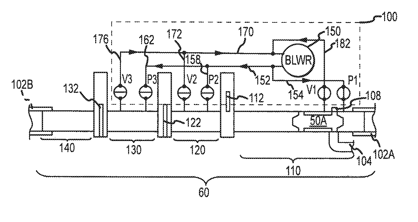
[0008]Another objective of the present invention is to provide a means for reliably reinitiating movement of a pneumatic carrier that has stopped in a pneumatic tube carrier system.
[0013]The gate member may be any element that is operative to move into and out of the internal bore of the pneumatic tube in order to at least partially engage a pneumatic carrier passing therethrough. That is, the gate member need only be operative to stop / prevent passage of a pneumatic carrier through the internal bore of the pneumatic tube. In one arrangement, the gate member is operative to be disposed into the internal bore while permitting a fluid flow through the internal bore. In another arrangement, the gate member prevents fluid flow through the internal bore when positioned within the internal bore of the pneumatic tube.
[0016]Generally, the fluid inlets and / or fluid outlets may extend through a side surface of the pneumatic tube to fluidly interconnect the blower to the internal bore of the pneumatic tube. As will be appreciated, ducting may extend between the fluid inlet and fluid outlet and the blower. In one arrangement, this ducting comprises a slip fit arrangement. In this regard, adjacent ducts utilize a friction fit that is free of mechanical fasteners therebetween. Such a slip fit duct arrangement may facilitate maintenance of the device.
[0018]To further facilitate the creation of a pressure differential across a stopped / stationary pneumatic carrier, the method may further include removing a fluid flow from the internal bore of a pneumatic tube at a second location that is proximate to a second end of the pneumatic carrier. This may create a pneumatic circuit where fluid flows from the blower through the outlet, through the internal bore of the pneumatic tube, through the inlet and back to the blower. Accordingly, fluid flowing around this pneumatic circuit may be applied across the stopped pneumatic carrier to create a pressure differential. Accordingly, this fluid flow may be utilized to reinitiate movement of the carrier. Furthermore, the flow volume may be varied through the pneumatic circuit if necessary to increase a pushing and / or pulling force utilized to initiate movement of the carrier.

Problems solved by technology

However, a more difficult situation arises when a carrier is being sent from a single tube location.
Further, if the carrier remains in a single tube awaiting launch, the carrier may interfere with incoming traffic.
However, stopping a carrier at such a location within a pneumatic network can lead to various complications.
One particular complication is that the carrier, once stopped, may become stuck within a pneumatic tube within the network and thereby require manual removal.
That is, it may be difficult to reinitiate movement of a stationary carrier within a pneumatic tube.
However, such systems have proved mechanically difficult to manufacture, pneumatically seal and maintain.
Further, due to the constraints of operating a conveyor belt within a pneumatic tube, the contact area between such a conveyor belt and a pneumatic carrier is generally small and may fail to provide enough force to initiate movement of a stationary carrier thereby requiring manual intervention.
In this regard, failure to reinitiate movement of a stationary carrier may require that a portion of the network or the entire network to be shut down for maintenance.

Method used


Image

  • Air powered storage device for pneumatic transport system
  • Air powered storage device for pneumatic transport system
  • Air powered storage device for pneumatic transport system

Examples


Embodiment Construction

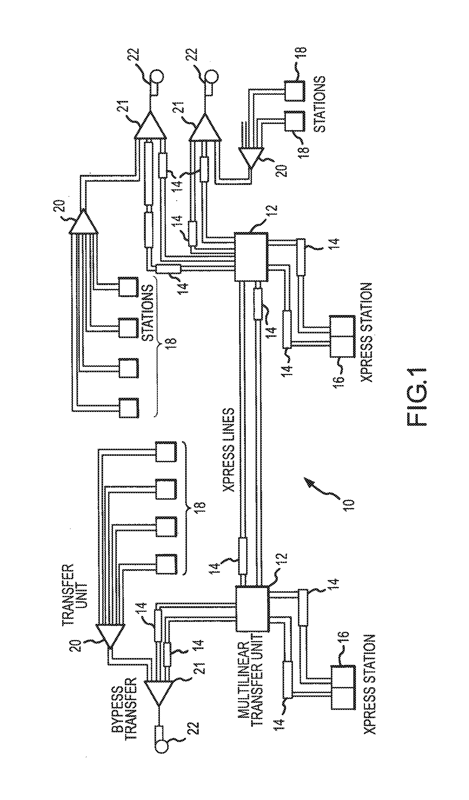
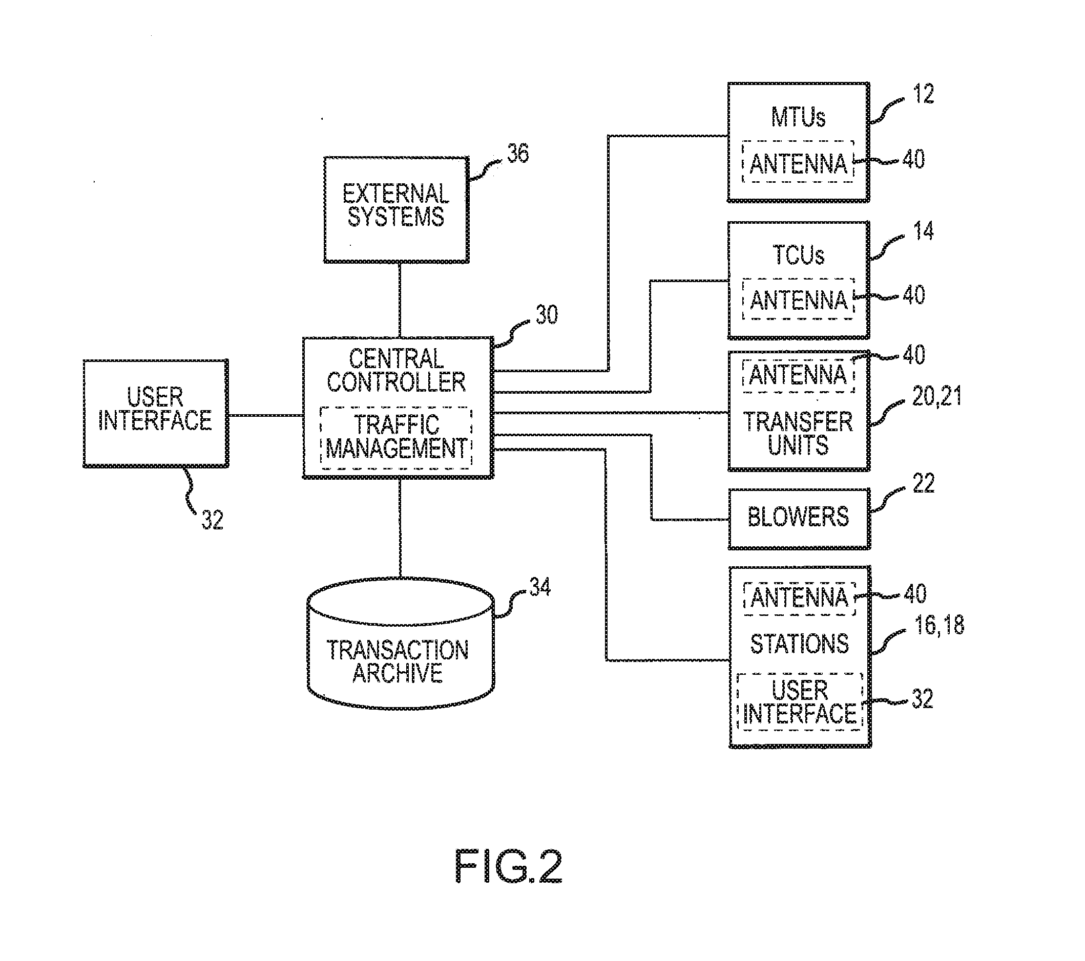
[0030]Disclosed in FIG. 1 is a system diagram for a pneumatic carrier system 10 within which the invention described herein is employable. In general, the pneumatic carrier system 10 transports pneumatic carriers between various user stations 16, 18, each such transport operation being referred to herein as a “transaction”. At each of the user stations 16, 18, a user may insert a carrier, select / enter a destination address / identification and a transaction priority, and then send the carrier. The system determines an optimum path to route the carrier and begins directing the carrier through the system.

[0031]Interconnected with each station 16, 18 is a transfer unit 20 which orders carriers arriving through different tubes from a different station 16, 18 into a single pneumatic tube. This pneumatic tube is further in connection with a vacuum by-pass transfer unit 21 (i.e., a turn around transfer unit) and a blower 22 that provides the driving pneumatic force for carrier movement. A se...


PUM


Abstract

An air powered storage device is provided that is operative to temporarily store pneumatic carriers within a pneumatic carrier system. Generally, the device includes a pneumatic tube that is sized to permit the passage of pneumatic carriers. A gate member is selectively positionable into and out of an internal bore of the pneumatic tube to impede movement of pneumatic carriers there through. The device further includes a blower having a first fluid inlet disposed on a first side of the gate member and a fluid outlet disposed on a second side of the gate member. The fluid inlet and outlet are fluidly interconnected to the internal bore of the pneumatic tube such that the blower is selectively operable to generate a fluid flow through the internal bore between the fluid outlet and the fluid inlet. Such fluid flow may be utilized to reinitiate movement of a stopped carrier.

Description

CROSS REFERENCE TO RELATED APPLICATION[0001]This application claims priority under 35 U.S.C. §119 to U.S. Provisional Application No. 60 / 644,850 entitled “Air Powered Linear Storage Device” and which was filed on Jan. 18, 2005, the contents of which are incorporated herein by reference.FIELD OF THE INVENTION[0002]The present invention relates generally to the field of pneumatic tube carrier systems, and more particularly to a system and method for storing and handling multiple carriers at an intermediate location within in a pneumatic tube carrier system.BACKGROUND OF THE INVENTION[0003]Pneumatic tube carrier systems are a well-known means for the automated transport of materials between, for example, an origination location to any one of a plurality of destination locations. A typical system includes a number of pneumatic tubes interconnected in a network to transport carriers between a number of user stations. Various blowers and transfer units provide the force and path control m...

Claims


Application Information

Patent Timeline
IPC IPC(8): B65G51/22
CPCB65G51/22B65G51/44
Inventor CASTRO, RAYMOND ANTHONYPODRACKY, JIMTRENCONSKY, ROBERT
Owner TRANSLOGIC
Learn More