Image printing device, control method, storing medium and program

A technology for image printing and printing media, applied in printing devices, memory systems, program control design, etc., can solve problems such as visually uneven images

Inactive Publication Date: 2003-01-15
CANON KK
View PDF11 Cites 8 Cited by
  • Summary
  • Abstract
  • Description
  • Claims
  • Application Information

AI Technical Summary

Problems solved by technology

This results in a visually uneven image

Method used


Image

  • Image printing device, control method, storing medium and program
  • Image printing device, control method, storing medium and program
  • Image printing device, control method, storing medium and program

Examples


no. 1 example

[0112] control device

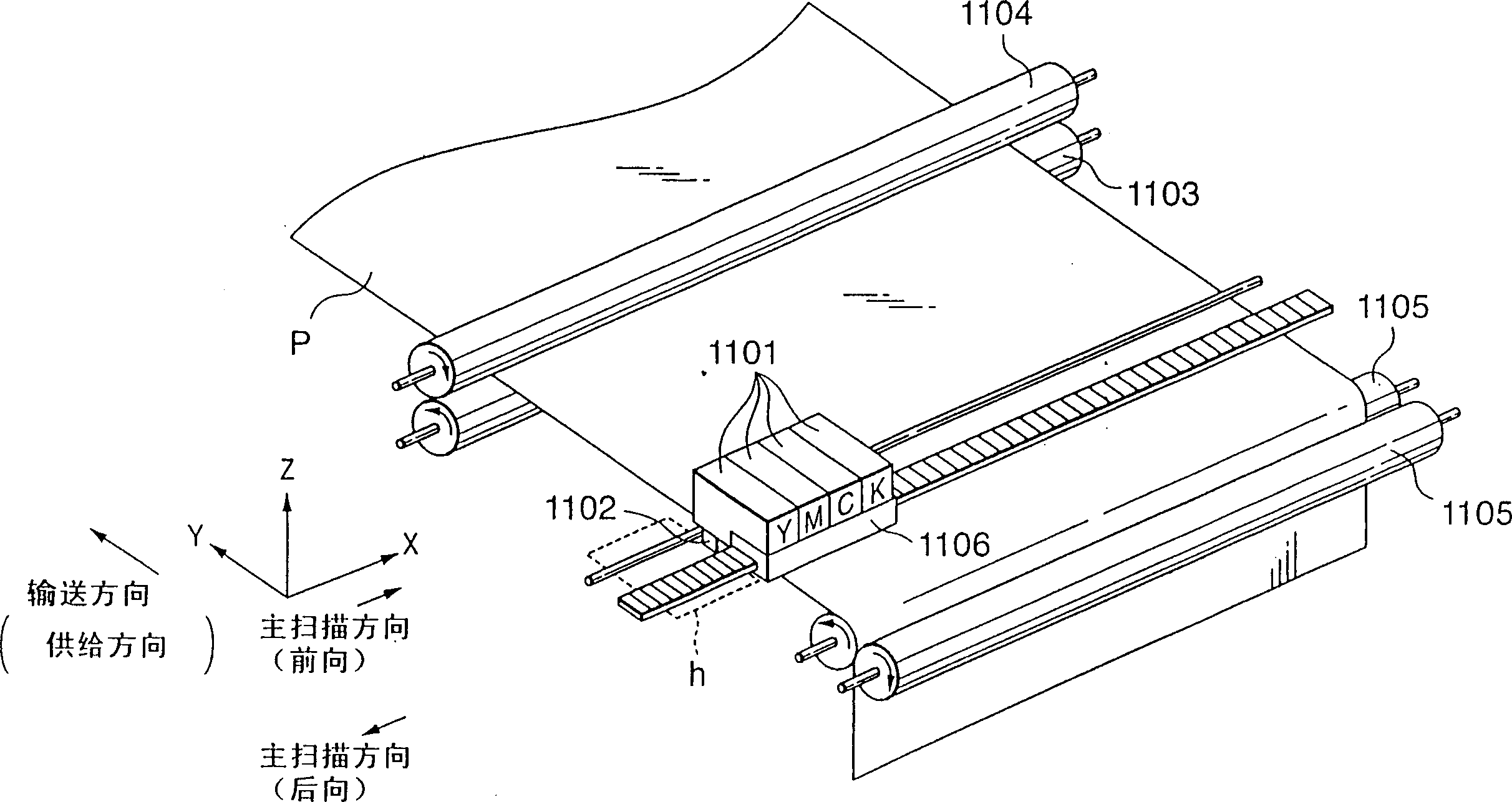
[0113] Image 6 is a block diagram showing the control device of the inkjet printer according to the first embodiment of the present invention. According to the mechanism of the inkjet printer of this embodiment and figure 1 is the same as the general printer shown in , so a duplicate description thereof is omitted.

[0114] exist Image 6 Among them, the CPU 600 executes control and data processing of each unit (to be described below) via the main bus 605 . More specifically, the CPU 600 performs head control, carriage drive control, and data processing via units (to be described below) according to programs stored in the ROM 601 (to be referred to Figure 7 and the accompanying figures are described).

[0115] RAM 602 is used as a work area for CPU 600 to perform data processing and the like. In addition to these memories, a hard disk and the like are installed.

[0116] The image input unit 603 has an interface connected to a host device (not ...

no. 2 example

[0164] An inkjet printer according to a second embodiment will now be described.

[0165] The mechanism, control device, and print head of the inkjet printer according to the second embodiment are the same as the mechanism of the inkjet printer described in the first embodiment ( figure 1 ), control device ( Image 6 ) and the print head ( Figure 7 and 8), so their repeated descriptions are omitted.

[0166] multi-pass printing mode

[0167] The multi-pass printing mode using the described inkjet printer and printhead will now be explained.

[0168] In the following description, the 4-pass printing mode in which the color nozzle row is divided into four parts by m=4 and the image is completed by four scanning operations will be divided into m (m is 2 or more) parts as the color nozzle row and the image is passed through An example of a multi-pass printing mode in which m scanning operations are performed will be described.

[0169] Features of the second embodiment will ...

no. 3 example

[0206] An inkjet printer according to a third embodiment will now be described.

[0207] The mechanism, control device, and print head of the inkjet printer according to the third embodiment are the same as the mechanism of the inkjet printer described in the first embodiment ( figure 1 ), control device ( Image 6 ) and the print head ( Figure 7 and 8), so their repeated descriptions are omitted.

[0208] multi-pass printing mode

[0209] The multi-pass printing mode using the described inkjet printer and printhead will now be explained.

[0210] In the following description, the 4-pass printing mode in which the color nozzle row is divided into four parts by m=4 and the image is completed by four scanning operations will be divided into m (m is 2 or more) parts as the color nozzle row and the image is passed through An example of a multi-pass printing mode in which m scanning operations are performed will be described.

[0211] Features of the third embodiment will now...


PUM


Abstract

Printing of a unit pixel (1/D = 1/600) in 4-pass printing (64 nozzles, and a total sheet supply amount of 62/600 in four operations) is exemplified in an image printing apparatus capable of printing a uniform, high-quality image while avoiding printing of a visually nonuniform image in multipass printing of two or more passes. A first pass printing dot (101) is printed using an Even nozzle by a sheet supply amount of 16/600 (even multiple of 1/D) while a carriage moves in the main scanning direction (main droplet and satellite land apart from each other). A second pass printing dot (102) is printed using an Odd nozzle by a sheet supply amount is 15/600 (odd multiple of 1/D) while the carriage moves in a direction opposite to the main scanning direction (main droplet and satellite land apart from each other). A third pass printing dot (103) is printed using an Odd nozzle by a sheet supply amount of 16/600 (even multiple of 1/D) while the carriage moves in the main scanning direction (main droplet and satellite land close to each other). A fourth pass printing dot (104) is printed using an Odd nozzle while the carriage moves in a direction opposite to the main scanning direction (main droplet and satellite land close to each other). By repeating this operation, satellites can be uniformly printed on the right and left of a unit pixel.

Description

field of invention [0001] The present invention relates to an image printing apparatus, a control method, a storage medium, and a program, and more particularly, to a method of uniform image printing in an inkjet printing apparatus that prints information by discharging ink onto a printing member. Background of the invention [0002] Printing equipment used to print images, etc. in printers, copiers, facsimile equipment, etc., or printing equipment used as print output devices in workstations or composite electronic devices including computers, word processors, etc., based on image information (including various output information such as character information) to print an image or the like on a printing member (hereinafter also referred to as a printing medium) such as paper or a thin plastic plate. [0003] Printing devices can be classified into inkjet type, pin point type, thermal type, laser beam type, etc. according to their printing methods. [0004] Among these prin...

Claims


Application Information

Patent Timeline
Patent Type & Authority Applications(China)
IPC IPC(8): B41J2/01B41J2/07B41J11/42
CPCB41J11/425B41J2/07
Inventor 中川喜统森山次郎神田英彦
Owner CANON KK
Why Eureka
Try Eureka