
Peak suppressing method and data transmission device

A peak value and threshold technology, applied in the field of data transmission devices, can solve the problems of reduced reception level, S/N deterioration, and impossibility of high-speed data transmission.

Inactive Publication Date: 2003-01-22
FUJITSU LTD
View PDF1 Cites 5 Cited by
  • Summary
  • Abstract
  • Description
  • Claims
  • Application Information

AI Technical Summary

Problems solved by technology

[0019] Although, reducing the transmission level can prevent saturation at the peak point, but after all, the reception level must also be reduced, so that the S / N is significantly deteriorated
take Figure 4 As shown in the structure, even if zero insertion is used to eliminate noise, S / N will still be negative, and high-speed data transmission cannot continue.

Method used


Image

  • Peak suppressing method and data transmission device
  • Peak suppressing method and data transmission device
  • Peak suppressing method and data transmission device

Examples


Embodiment Construction

[0052] Embodiment 1 of the data transmission device of the present invention consists of Figure 6 give. Embodiment 1 of the data transmission device also discloses Embodiment 1 of the peak suppression method of the present invention. according to Figure 6 , The data transmission device includes: a code conversion unit 1, a signal point generation unit 2, and an inverse FFT unit (IFFT) with the function of adding a guard time GT. 3. Zero insertion unit 4, peak suppression unit 21, roll-off filter (ROF) 5, modulation unit (MOD) 6, digital-to-analog converter (D / A) 7# low-pass filter (LPF) 8, sending clock Pulse generation unit (TX-CLK) 9. Each of the aforementioned units constitutes a sending unit. Among them, the code conversion unit includes SCR (scrambler), S / P (serial-to-parallel conversion), G / N (Grey code / natural code conversion) and sum calculation and other units. In addition, TX-line represents a transmission line.

[0053]The data transmission device of the pre...


PUM


Abstract

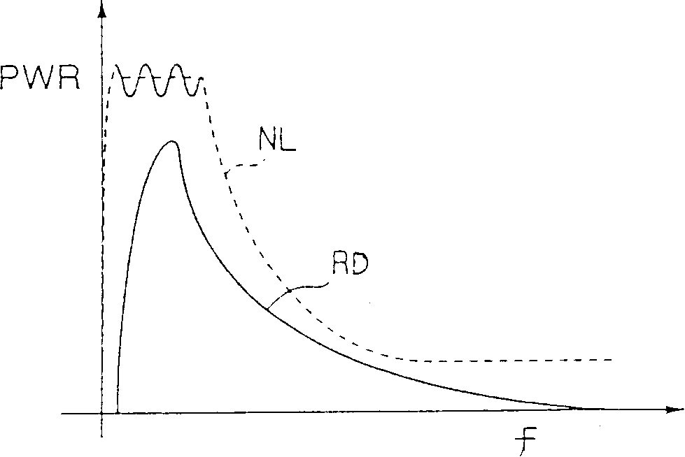
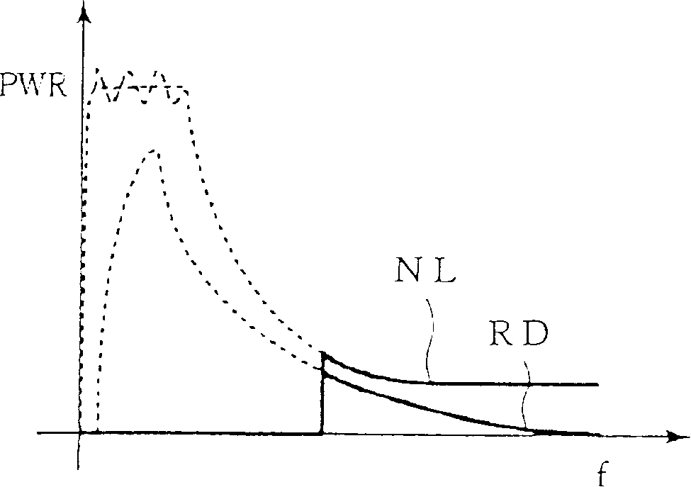
A peak suppression method detects a peak value exceeding a threshold value of a transmitting signal, forms a peak value prediction signal which is limited to a noise cancelling frequency band of a receiving end, based on the detected peak value of the transmitting signal, and subtracts the peak value prediction signal from the transmitting signal.

Description

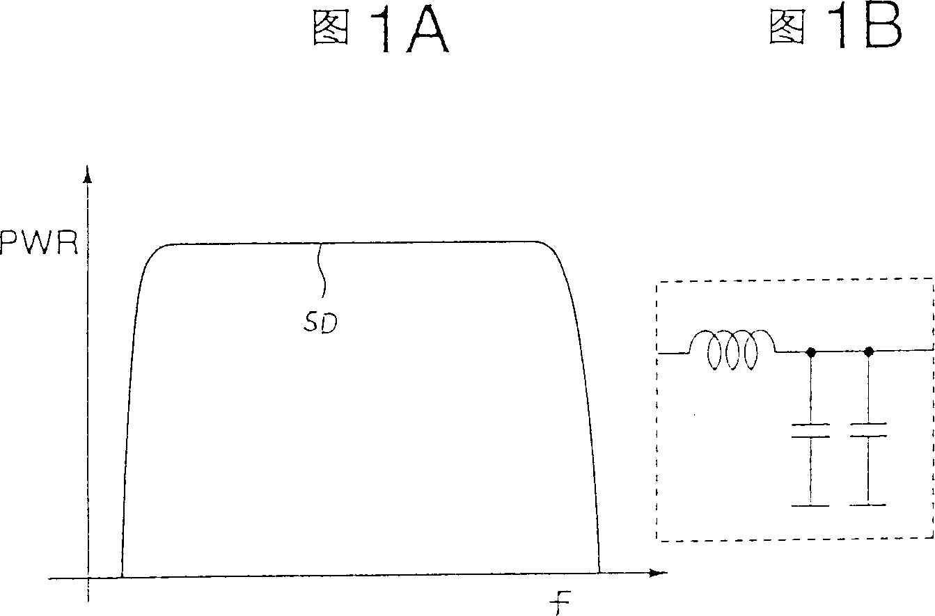
technical field [0001] The present invention relates to a peak suppression method and a data transmission device, in particular to a peak suppression method for suppressing transmission power peaks in a system for transmitting data at high speed with multiple carriers to avoid S / N deterioration at the receiving end, and a method for suppressing transmission signals during data transmission peak suppressed data transfer device. [0002] The multi-carrier data transmission here involves the wired ADSL (Asymmetric Digital Subscriber Line) and SDSL (Symmetrical Data Subscriber Line) fields, or the wireless OFDM field, the optical signal WDM field, and the like. Background technique [0003] The priority document of this application is Japanese Invention Patent Application No. 2001-186273 filed with the Japan Patent Office on June 20, 2001, and reference is made to the contents thereof. [0004] In systems that transmit data through wired, wireless or even optical transmission l...

Claims


Application Information

Patent Timeline
Patent Type & Authority Applications(China)
IPC IPC(8): H04J11/00H04B1/10H04B3/54H04J1/00H04L27/26
CPCH04L27/2624H04J1/00
Inventor 加来尚平尾恭子
Owner FUJITSU LTD
Learn More