Cone-disk clutch

A clutch and cone-disc technology, applied in the field of machinery, can solve the problems of insufficiency of the separation control mechanism, reduced manufacturing cost, large separation control force, etc., and achieves the effect of eliminating the following phenomenon, reducing the weight and achieving a good separation effect.

Inactive Publication Date: 2003-02-05
葛玉明
View PDF0 Cites 5 Cited by
  • Summary
  • Abstract
  • Description
  • Claims
  • Application Information

AI Technical Summary

Problems solved by technology

[0003] The task of the present invention is to provide a cone-disk clutch with a new structure, which can overcome the shortcomings of the traditional cone-disk clutch, such as relatively large radial size, insufficient separation control mechanism, and large separation control force. The new structure of the cone-disk clutch It should exceed the traditional conical disc clutch in many aspects, for example, its radial size is smaller; the combination effect should be better, and no slippage will occur; the separation control mechanism is simple and compact; compared with the traditional flat disc clutch, it can be separated very It should be clear and completely eliminate the phenomenon of follow-up; it should also be simpler and more compact, and its weight should be greatly reduced; its maintenance and debugging should also be very simple, easy to master, and easy to operate for ordinary users; at the same time, its manufacturing cost should be relatively large. Reduced, the weight has been significantly reduced; finally, the work of the new structure should be very reliable, and the separation control device will not be damaged due to high-speed operation and severe friction

Method used


Image

  • Cone-disk clutch
  • Cone-disk clutch
  • Cone-disk clutch

Examples


Embodiment 1

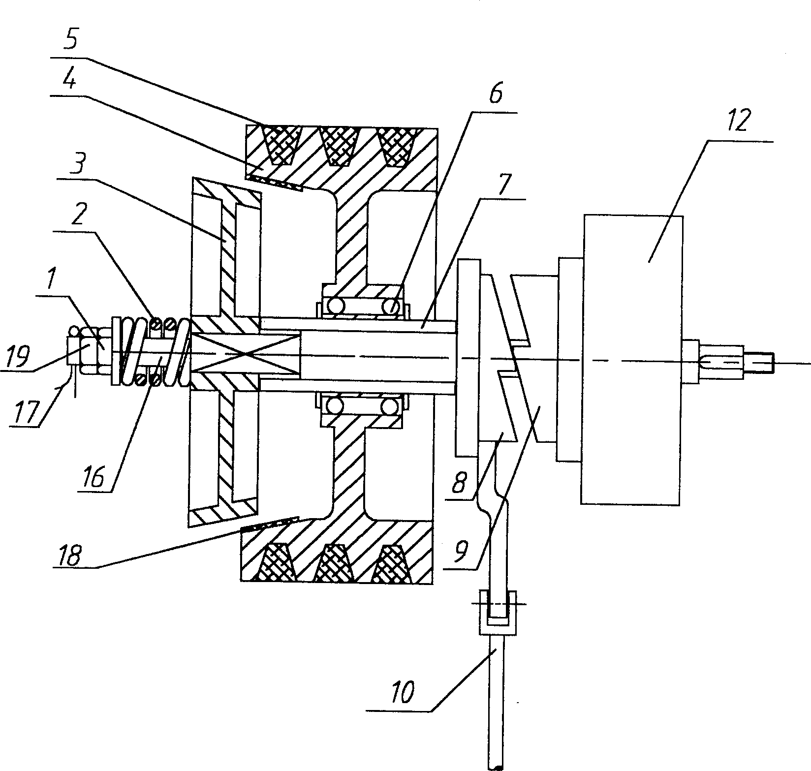
[0011] Embodiment 1, with reference to figure 1: The clutch is disengaged. The clutch part in the figure has been cut horizontally, 16 is the driven shaft, the driven disc 3 is connected with the driven shaft 16 through a spline, the driven disc 3 can move in series on the driven shaft 16, but cannot rotate freely; The disk 4 is arranged between the driven disk 3 and the separation operation mechanism, that is, the separation claw 8 and the bearing cover 9. The driving disk 4 is fixed to the driven shaft 16 through the bearing 6. There are retaining rings 20 on both sides of the bearing 6 to limit the displacement of the bearing 6. , the driving disc 4 can rotate freely on the driven shaft 16, and the power of the engine drives the driving disc 4 to rotate through a flexible transmission device such as a chain or a V-belt 5; , the opposite helical tooth surface meshes with the bearing cover 9 assembled on the gearbox, and the lower part of the separation claw is twisted with ...

Embodiment 2

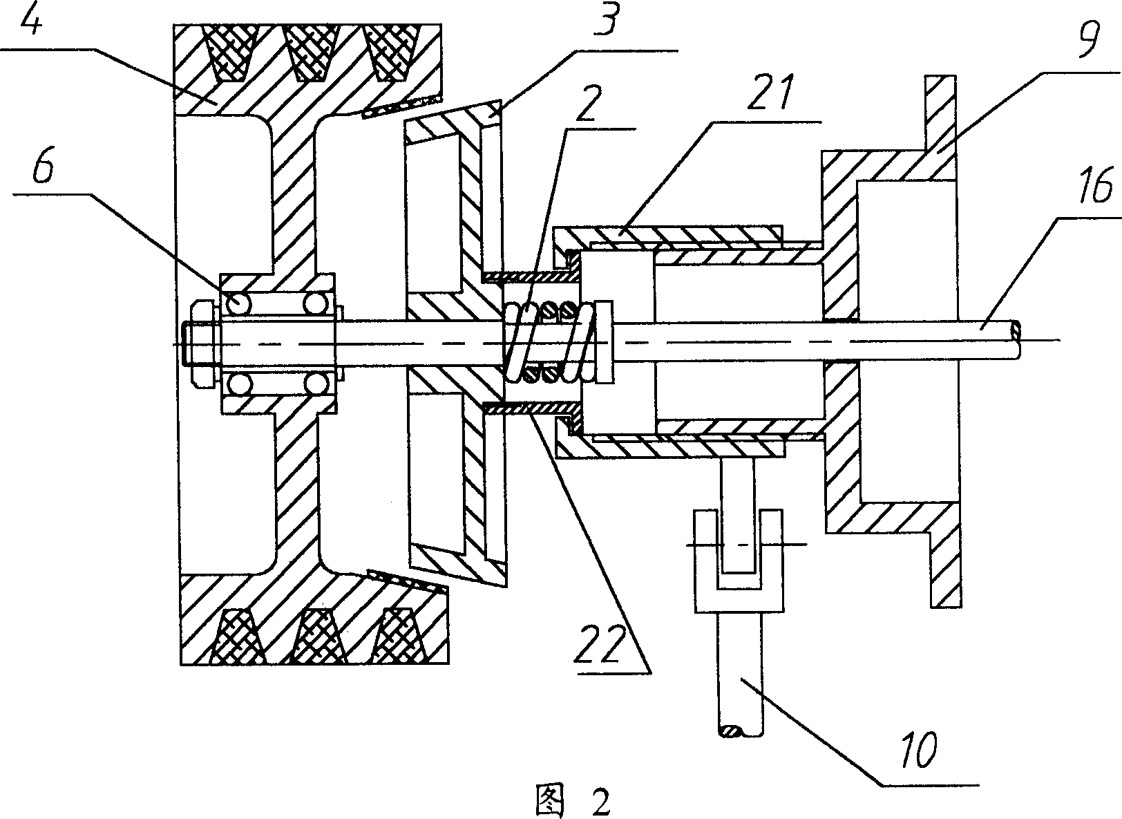
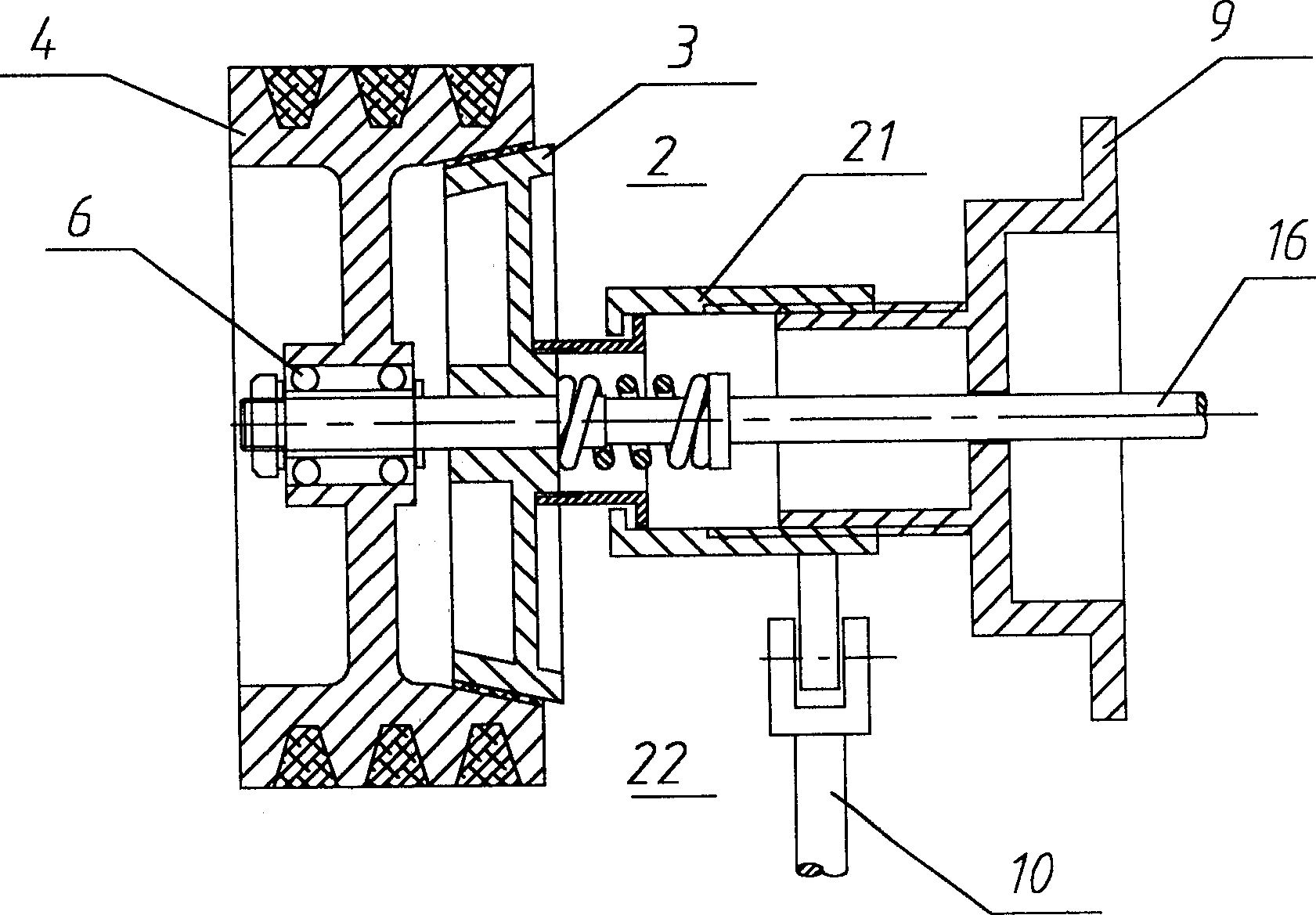
[0012] Embodiment 2, with reference to Fig. 2, 3: the driven disk 3 is arranged between the driving disk 4 and the separation control mechanism, and a screw sleeve 21 that can be twisted is connected in series on the driven shaft 16, and the outer circle or the inner circle of the screw sleeve 21 Processing is threaded, and there is also a bearing cap 9 that is sleeved on the driven shaft 16 but is fixed on objects such as a gear box or a frame corresponding to it on one side of the screw sleeve 21, and the inner circle of the bearing cap 9 Or the outer circle is also processed with the same thread as the screw sleeve 21, the screw sleeve 21 and the bearing cover 9 are screwed together through the thread similar to bolts and nuts, and the axial displacement of the screw sleeve 21 is realized by pulling the pull rod 10 on the screw sleeve 21 , there is a screw tube 22 on the driven disk 3 to fasten and fit with it, the screw tube 22 runs through the screw sleeve 21, and when the...

Embodiment 3

[0013] Embodiment 3, with reference to Figure 4 : The clutch is disengaged. A bow-shaped push rod 23 has a collar 24 and 25 at both ends, the collar 24 is set on the separation claw 8, and the collar 25 is set in the control groove of the driven disk 3; pulling the pull rod 10 and the separation claw 8, is received Under the action of the screw force, the bow-shaped push rod 23 will push the driven disc 3 away from the driving disc 4, and the clutch will be separated; otherwise, the pull rod 10 and the separation claw 8 will be released, and the separation claw 8 will no longer apply force to the bow-shaped push rod 23 , under the action of the force of the large spring 2 outside the driven disc 3, the bow-shaped push rod 23 moves freely toward the gearbox 12 side, the driven disc 3 is tightly pressed into the driving disc 4, and the clutch is combined.


PUM


Abstract

The present invention relates to a concial disk clutch, including conical driving disk and driven disk which are set on shaft, both are holden together by spring, at the same time equipped with control mechanism. It is characterized by that the control mechanism adopts screen separator whose structure is as follows: one end of driven shaft is equipped with disengaging claw, an axial channel is set on the driven shaft, in said axial channel an ejector pin is placed, one end of said ejector pin is placed against the dieengaging claw, and its another end is placed against driven disk, and the driving disk and driven disk are placed on same shaft.

Description

technical field [0001] The invention belongs to the field of machinery and relates to a conical friction clutch, referred to as a cone-disc clutch. Background technique [0002] In the field of machinery, the use of clutches is very extensive, and it is mainly used for the separation and combination of shafts during machine operation. According to the combination elements, there are mainly two types: friction type and meshing type. The friction type is widely used in automobiles, agricultural vehicles, tractors, And various agricultural machinery driven by tractors. But the most widely used at present is the flat disc friction clutch in the friction clutch, especially the multi-disk flat disc friction clutch wherein. The conical friction clutch (hereinafter referred to as the cone disc clutch) is used less. Because the traditional concept thinks: the radial size of the conical disc clutch is far less compact than the multi-disc flat disc friction clutch. The reason for t...

Claims


Application Information

Patent Timeline
Patent Type & Authority Applications(China)
IPC IPC(8): F16D13/26
Inventor 葛伟岸葛玉明葛桂萍
Owner 葛玉明
Why Eureka
Try Eureka