Method and equipment for measuring pulse pressure at adjacent points

A technology for measuring points and pulse pressure, applied in the direction of catheters, etc., can solve problems such as inability to calculate dynamic compliance, loss of pressure changes, etc.

Inactive Publication Date: 2003-02-12
E MED BIOTECH
View PDF0 Cites 4 Cited by
  • Summary
  • Abstract
  • Description
  • Claims
  • Application Information

AI Technical Summary

Problems solved by technology

However, since the pressure sensor and the displacement driver are integrated, when the pressure sensor moves, the pressure change at this point is also lost, resulting in the inability to calculate the dynamic compliance
[0017] However

Method used


Image

  • Method and equipment for measuring pulse pressure at adjacent points
  • Method and equipment for measuring pulse pressure at adjacent points
  • Method and equipment for measuring pulse pressure at adjacent points

Examples


Embodiment Construction

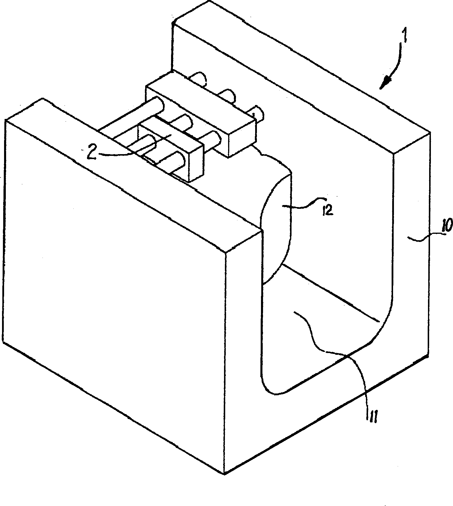
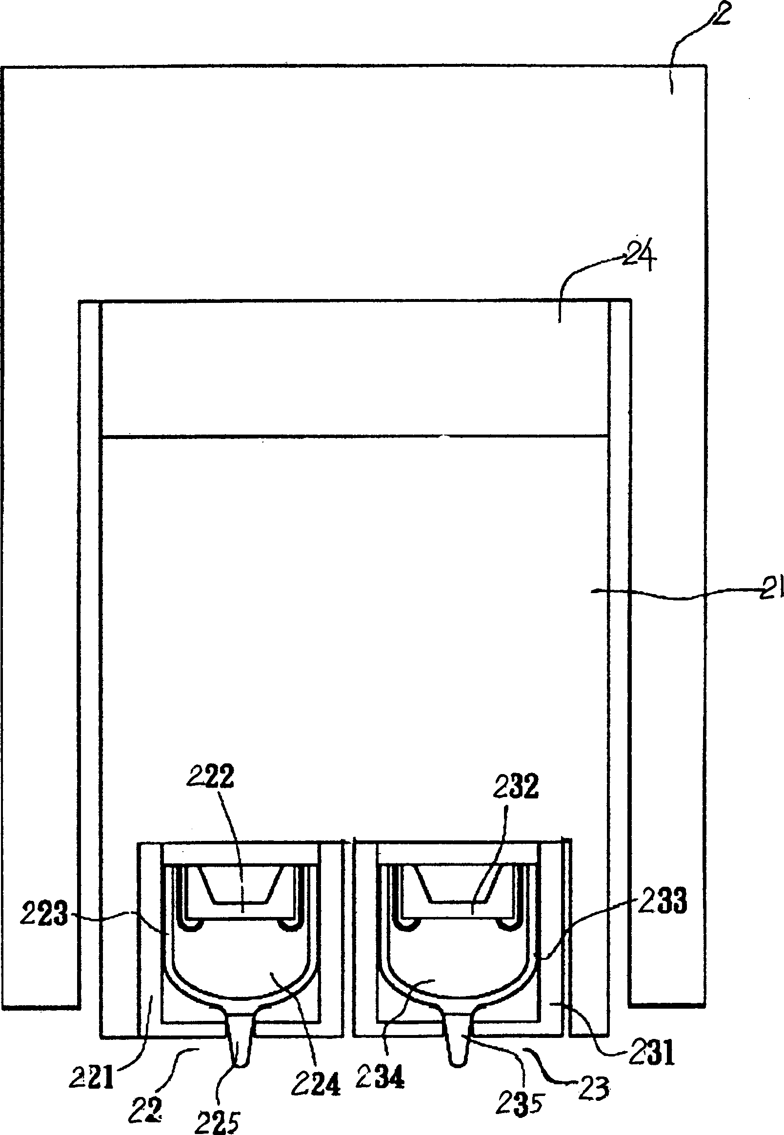
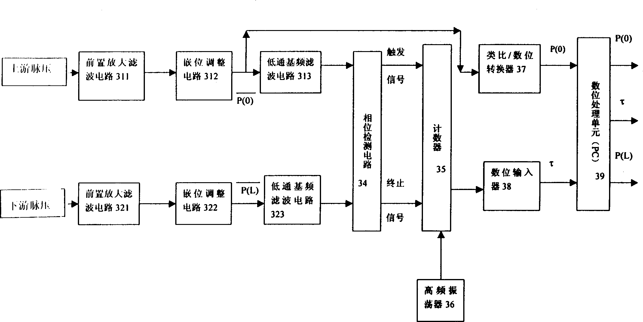
[0046] see figure 1 , figure 2 , image 3 , as can be seen from the figure, the composition of the measuring device of pulse pressure at two adjacent measuring points of the present invention includes:

[0047] A wrist immobilization device 1, the wrist immobilization device 1 has a base 10, and the base 10 is provided with an accommodating portion 11 for the user to place the wrist on the wrist with the wrist radial artery facing upwards. In the accommodating portion 11 , there are inflatable pouches 12 on both sides of the accommodating portion 11 , and the cuffs 12 are inflated to clamp and fix the wrist without compressing the radial artery of the wrist.

[0048] A pressure sensing device 2, which is arranged on the base 10 of the wrist immobilization device 1, has a seat 21 at the position corresponding to the radial artery, please refer to figure 2 , the seat body 21 is driven by a drive assembly 24 to press down on the radial artery of the wrist, the drive assembly 2...


PUM


Abstract

A method for measuring the pulse pressure of two adjacent points and its device are disclosed. This method includes such steps as arranging two pressure sensors on a upstream point and a downstream point of the same blood vessel at a spacing of distance long the blood flow direction, measuring their pulse pressures and waveform variation, detecting the delay time of pulse wave between them by a delay detecting circuit, measuring the upstream pulse pressure, and calculating the downstream pulse pressure.

Description

Technical field: [0001] The invention is related to the diagnosis of human health status, in particular a method and device for measuring pulse pressure at two adjacent measurement points of blood vessels in the same part of the human body. Background technique: [0002] At present, various pulse wave measurement methods are based on measuring the pulse pressure and its waveform changes as a message for judging the health status, or converting the pulse pressure into a frequency spectrum for analysis. In addition to the measurement of pulse pressure, There are also methods such as measuring blood flow with Doppler ultrasound and measuring blood flow velocity with infrared ray sensing red blood cell moving speed, but these methods can only obtain a single message respectively, and obtain multiple messages asynchronously. However, a single signal of pulse pressure, blood flow or flow velocity is not enough to represent all the heart and blood vessel states, because under the s...

Claims


Application Information

Patent Timeline
IPC IPC(8): A61B5/02
Inventor 林钦裕
Owner E MED BIOTECH
Why Eureka
Try Eureka