
Control method with substitution mode ejection to pressure-relaining changeover point

A control method and switching point technology, which is applied in the field of injection to pressure holding switching point control with alternative modes, and can solve problems such as sag, clamping unit overload, error, etc.

Inactive Publication Date: 2003-03-05
NAT KAOHSIUNG UNIV OF SCI & TECH
View PDF2 Cites 6 Cited by
  • Summary
  • Abstract
  • Description
  • Claims
  • Application Information

AI Technical Summary

Problems solved by technology

Both are currently standard equipment for injection molding machines, but their results are easily affected by interference such as oil temperature fluctuations, mechanical movement errors, and plastic unevenness, resulting in large errors, resulting in too early or delayed switching timing; The third switching method is the fixed pressure switching method. For the injection molding machine driven by hydraulic pressure, there are three modes of switching methods: hydraulic pressure, nozzle pressure and mold cavity pressure, but this fixed pressure switching method is still often used. The phenomenon of poor switching occurs; the fourth is the switching method using the cavity pressure to calculate the filling volume saturation point. Although the fuzzy control theory is used for its control law, it is more robust, but it is still affected by the position of the pressure sensor and the special model. Affected by the waveform characteristics of the cave pressure
[0006] If the above four methods of injection switching and holding pressure are switched too early, the Figure 4 As shown, often make the product undersized or dented; while delay switching is as Figure 5 As shown, it is often accompanied by the risk of the mold cavity being highly squeezed. In addition to the adverse effects on the size and burr, it may also cause the main cause of the deformation of the mold cavity edge and the overload of the clamping unit, which in turn has a permanent impact on the guide post of the injection machine. damage, so it is practically impossible to achieve consistent quality requirements stably

Method used


Image

  • Control method with substitution mode ejection to pressure-relaining changeover point
  • Control method with substitution mode ejection to pressure-relaining changeover point
  • Control method with substitution mode ejection to pressure-relaining changeover point

Examples


Embodiment Construction

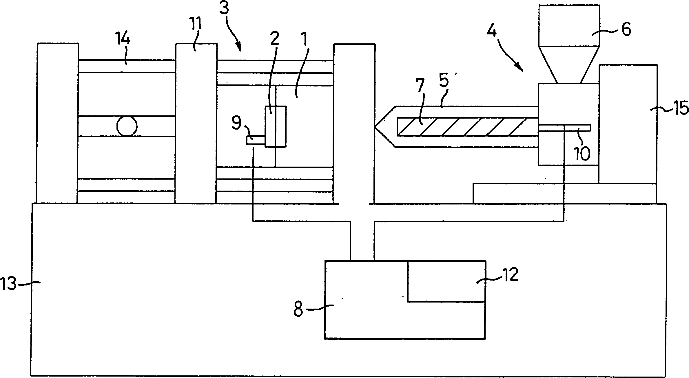
[0018] like figure 1 The injection molding machine shown includes a pair of forming molds 1 and mold cavities 2, a set of mold clamping mechanisms 3 responsible for the movement of mold opening and closing, and a set of injection units 4 that provide the functions of plasticizing and injecting plastic materials, which contain melt glue There is a hopper 6 above the barrel 5, and the plastic injection screw 7 in the melt barrel 5 can rotate and reciprocate. The movement of the injection screw 7 is controlled by the controller 8 of the injection molding machine. The cavity pressure installed in the cavity The sensor 9 is connected to the controller 8 .

[0019] The injection molding cycle starts when the plastic material is fed into the melt barrel 5 through the hopper 6, melted by the rotation of the injection screw 7 and retreated toward the hopper 6, and the metering action is completed. At this time, the melted glue is placed in the The front edge of the injection screw 7,...


PUM


Abstract

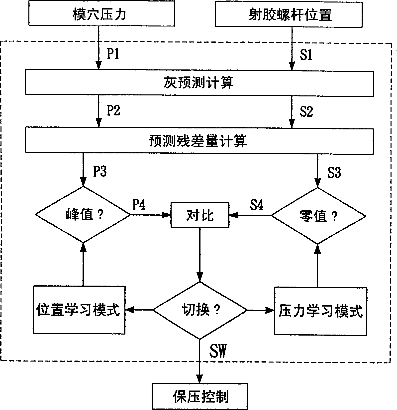
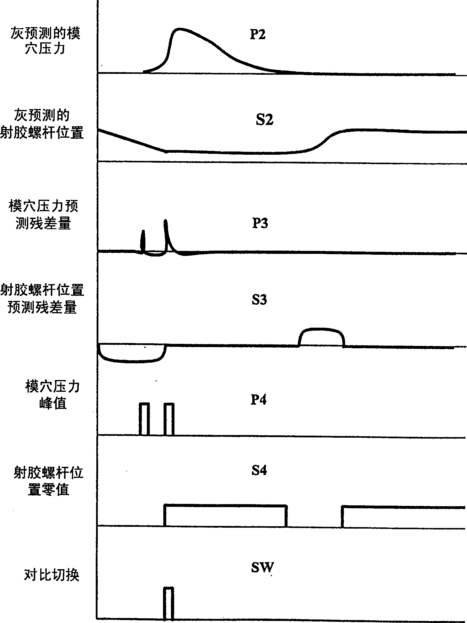
A die cavity pressure sensor is set in the forming die of ejection forming machine, a rubber-jetting screw rod position sensor is mounted on the rubber-jetting screw rod, in the power of starting ejection to switching to retain pressure the substitution mode control method is always in starting state, in which, after the signal P1 of die cavity pressure sensor and S1 rubber-jetting screw rod position sensor are picked up, a grey-level predictive mathematical model is used to respectively estimate next point P2 and S2 by using two points of every signal, and they are their actual measured values are subtrated to obtain precitive residual quantities P3 and S3, then the time sequence curves formed by using P3 and S3 can be used to find out the die cavity pressure predictive residual quantitypeak value P4 and screw rod position predictive residual quantity peak value S4.

Description

technical field [0001] The present invention is a method for controlling the switching point from injection to holding pressure with an alternative mode, which is applied to the determination of the switching timing from the speed-controlled injection stage to the pressure-controlled holding stage of the injection molding machine in the molding process, and if one of them When one group is set as the main switching reference, the other group enters the statistical learning mode, and if one group fails, this control method can automatically lock to a more stable group for switching point control. Background technique [0002] The injection molding method is a periodic process technology, and its steps are roughly divided into the mold closing process (Clamping), the injection process (Injection), the holding and plasticizing process (Holding and Plasticizing), the cooling and mold opening ejection process (Cooling and Ejection) ), the injection molding machine is controlled b...

Claims


Application Information

Patent Timeline
IPC IPC(8): B29C45/76
Inventor 黄明贤陈克昌
Owner NAT KAOHSIUNG UNIV OF SCI & TECH
Learn More