Electromagnetic drive dislocation micromechanical variable light attenuator

An electromagnetic drive, electromagnetic drive coil technology, applied in the direction of light guide, optics, instruments, etc., can solve the problems of increased driver travel and power consumption, practical difficulties, packaging and aligning optical fibers, etc., to achieve a large dynamic range, easy to array The effect of simplified packaging, structure and optical path

Inactive Publication Date: 2003-03-12
SHANGHAI JIAO TONG UNIV
View PDF0 Cites 10 Cited by
  • Summary
  • Abstract
  • Description
  • Claims
  • Application Information

AI Technical Summary

Problems solved by technology

However, the manufacturing process of the light-blocking sheet and its driver described in this article is relatively complicated and easily damaged. There are also strict requirements on the distance between the input and output fibers. 20 microns, resulting in large insertion loss, so it is difficult to package and align the optical fiber, and the yield of device production is very low
Moreover, in order to prevent the light-blocking sheet from blocking the beam propagating between the input and output fibers in the initial state and causing a large insertion loss, it is necessary to set a relatively small distance between the initial position of the light-blocking sheet and the position where the beam starts to be blocked in the drive stroke. Large adjustment margin, and although it needs to consume energy to adjust the position of the light barrier in this part of the adjustment margin, the attenuation cannot be adjusted, which leads to an unnecessary increase in the required drive stroke and power consumption. At the same time, the electrostatic drive The voltage is as high as 30V, it is difficult to be compatible with the working voltage of integrated circuits, so there are still great difficulties in practical application

Method used


Image

  • Electromagnetic drive dislocation micromechanical variable light attenuator
  • Electromagnetic drive dislocation micromechanical variable light attenuator

Examples


Embodiment Construction

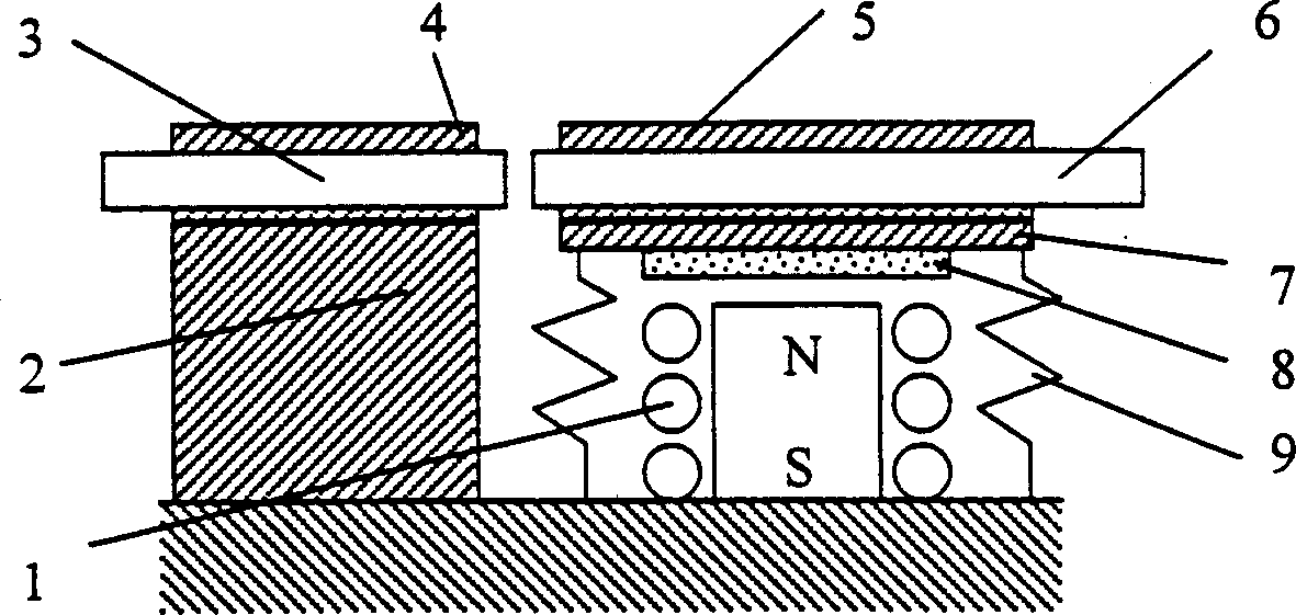
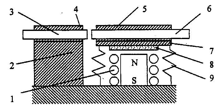
[0008] Such as figure 1 As shown, the present invention mainly includes: an electromagnetic drive coil 1, a base 2, optical fibers 3 and 6, positioning grooves 4 and 5, a movable platform 7, a magnetic body 8 and an elastic body 9, and the optical fibers 3 and 6 are respectively fixed on the base 2 and In the positioning grooves 4 and 5 on the movable platform 7, the movable platform 7 and the magnetic body 8 are fixed together, the base 2 and the movable platform 7 are connected by an elastic body 9, and the movable platform 7 moves up and down relative to the base 2 or / And rotate, the base 2 is fixed with the electromagnetic drive coil 1.

[0009] Through the deformation of the elastic body 9 under the action of the electromagnetic driving force, the upper and lower positions of the base 2 and the movable platform 7 are adjusted, the radial distance between the optical fibers 3 and 6 or / and the angle between the two axes are changed, and the optical properties of the optica...


PUM


Abstract

An electromagnetically driven dislocation-type micromechanical variable light attenuator is composed of electromagnetic drive coil, base, two optical fibres, locating slot, movable platform, magnet and elastomer. Its advantages are simple structure, low insertion loss (lower than 1 db), high echo loss (greater than 60 db), wide dynamic range (greater than 50 db), and low cost.

Description

technical field [0001] The invention relates to an optical attenuator, in particular to an electromagnetically driven dislocation type micromechanical variable optical attenuator, which belongs to the field of optical fiber communication. Background technique [0002] In recent years, with the development of all-optical network technology in optical fiber communication, variable optical attenuators are being used more and more widely. The all-optical network puts forward strict comprehensive performance requirements on the volume, cost, power consumption, and adjustment performance of the variable optical attenuator. Traditional mechanical variable optical attenuators can no longer meet the requirements of all-optical networks for optical fiber communication devices due to their shortcomings such as large size, high cost, and slow response speed. However, the variable optical attenuator produced by micromachining technology developed based on integrated circuit technology h...

Claims


Application Information

Patent Timeline
Patent Type & Authority Applications(China)
IPC IPC(8): G02B6/00G02B6/26G02B26/02G02F1/09
Inventor 戴旭涵赵小林蔡炳初
Owner SHANGHAI JIAO TONG UNIV
Why Eureka
Try Eureka