Optical device, mfg. method thereof and projector

A technology for an optical device and a dimming device, which is applied in the directions of optics, projection devices, optical components, etc., can solve the problems such as the large influence of the position deviation of the dimming device, the difficulty of adjusting the position of the dimming device, and the increase in manufacturing cost, and reduce the manufacturing cost. Cost, simple structure, the effect of reducing the manufacturing cost

Inactive Publication Date: 2003-03-12
SEIKO EPSON CORP
View PDF3 Cites 11 Cited by
  • Summary
  • Abstract
  • Description
  • Claims
  • Application Information

AI Technical Summary

Problems solved by technology

Therefore, it is difficult to adjust the position of the dimming device, and at the same time, the positional deviation of the pin or the spacer has a great influence on the positional deviation of the dimming device.
This problem can lead to increased manufacturing costs or reduced image quality

Method used


Image

  • Optical device, mfg. method thereof and projector
  • Optical device, mfg. method thereof and projector
  • Optical device, mfg. method thereof and projector

Examples


no. 1 Embodiment approach

[0180] Hereinafter, a first embodiment of the present invention will be described with reference to the drawings.

[0181] (1. The main structure of the projector)

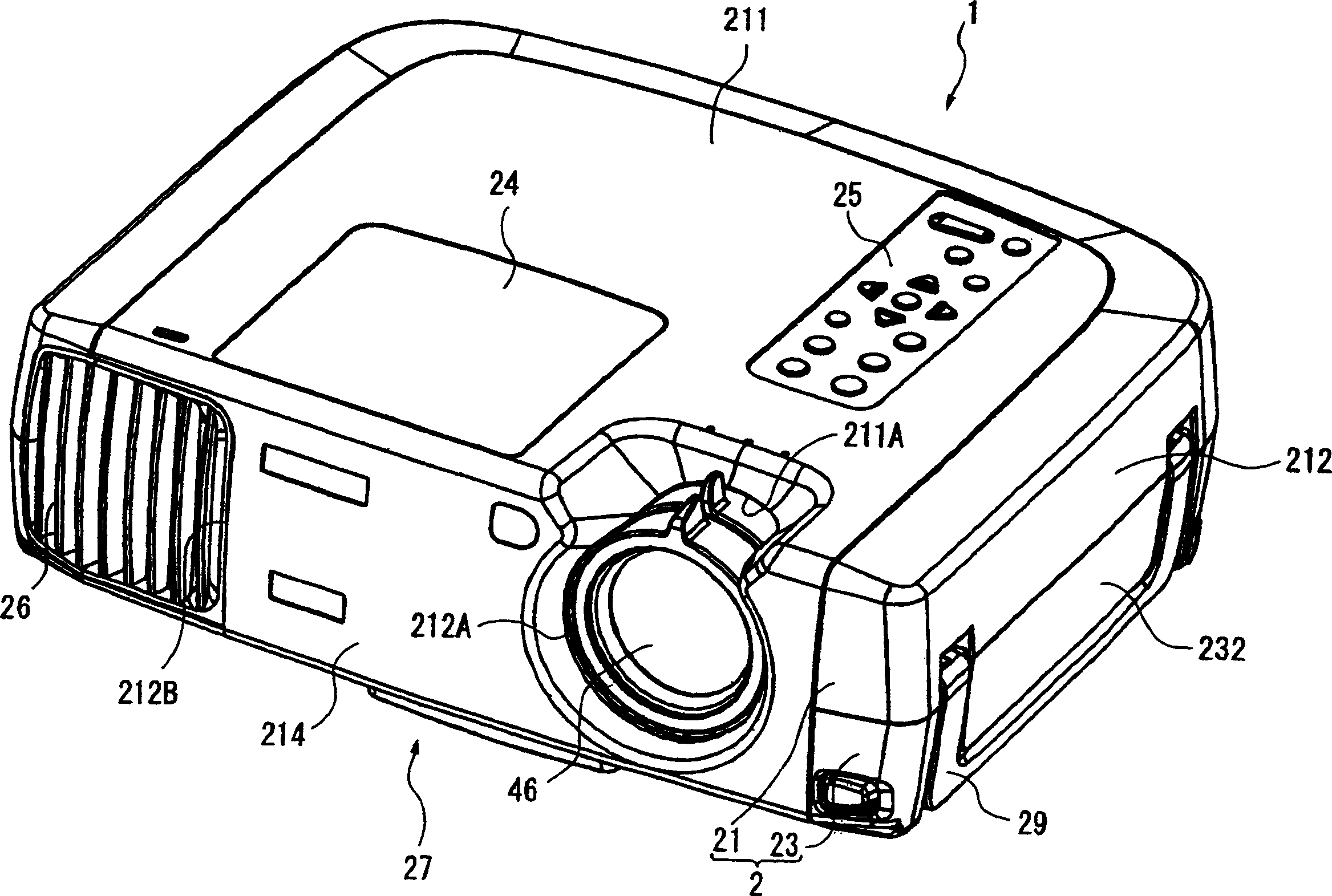
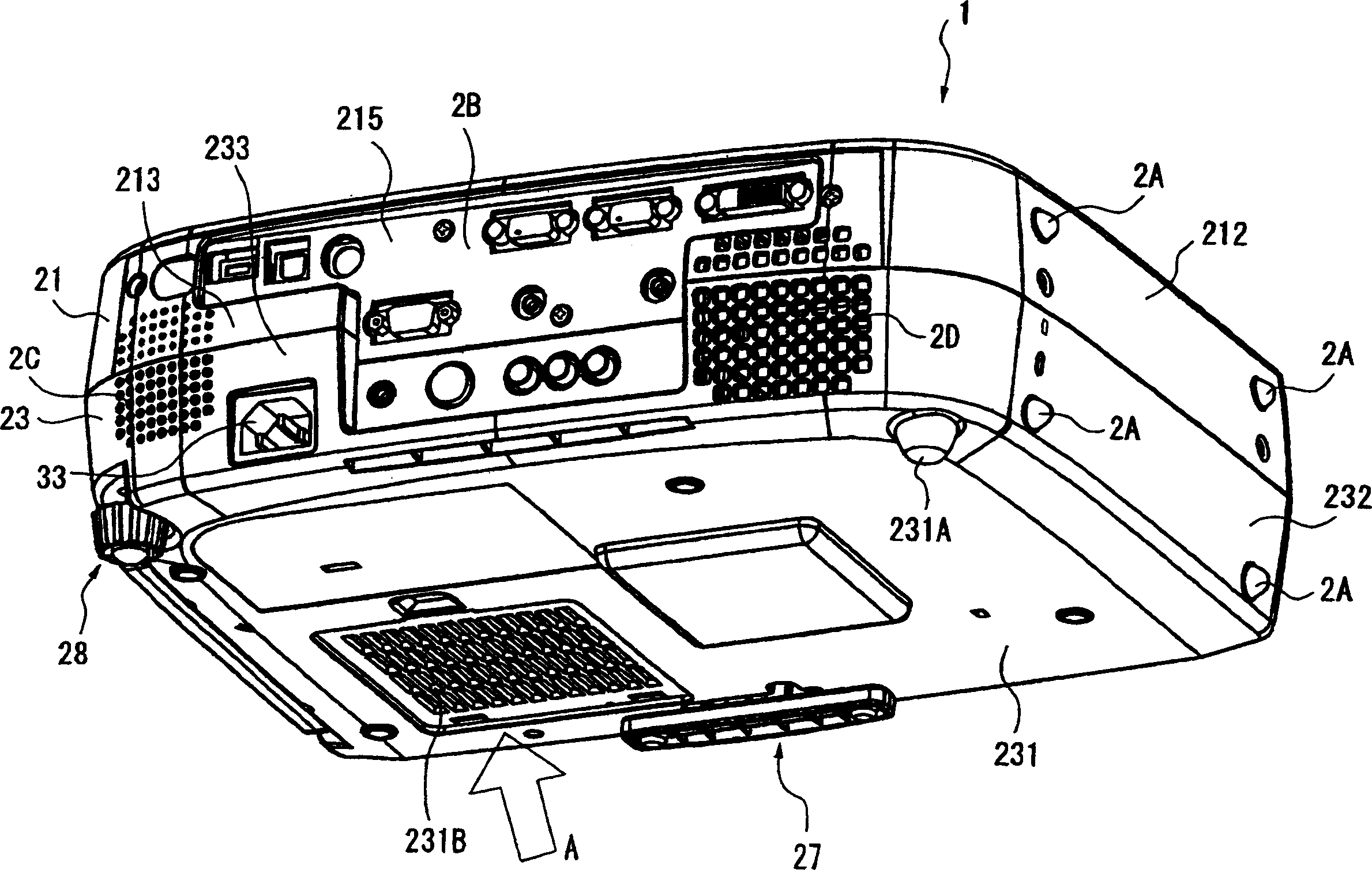
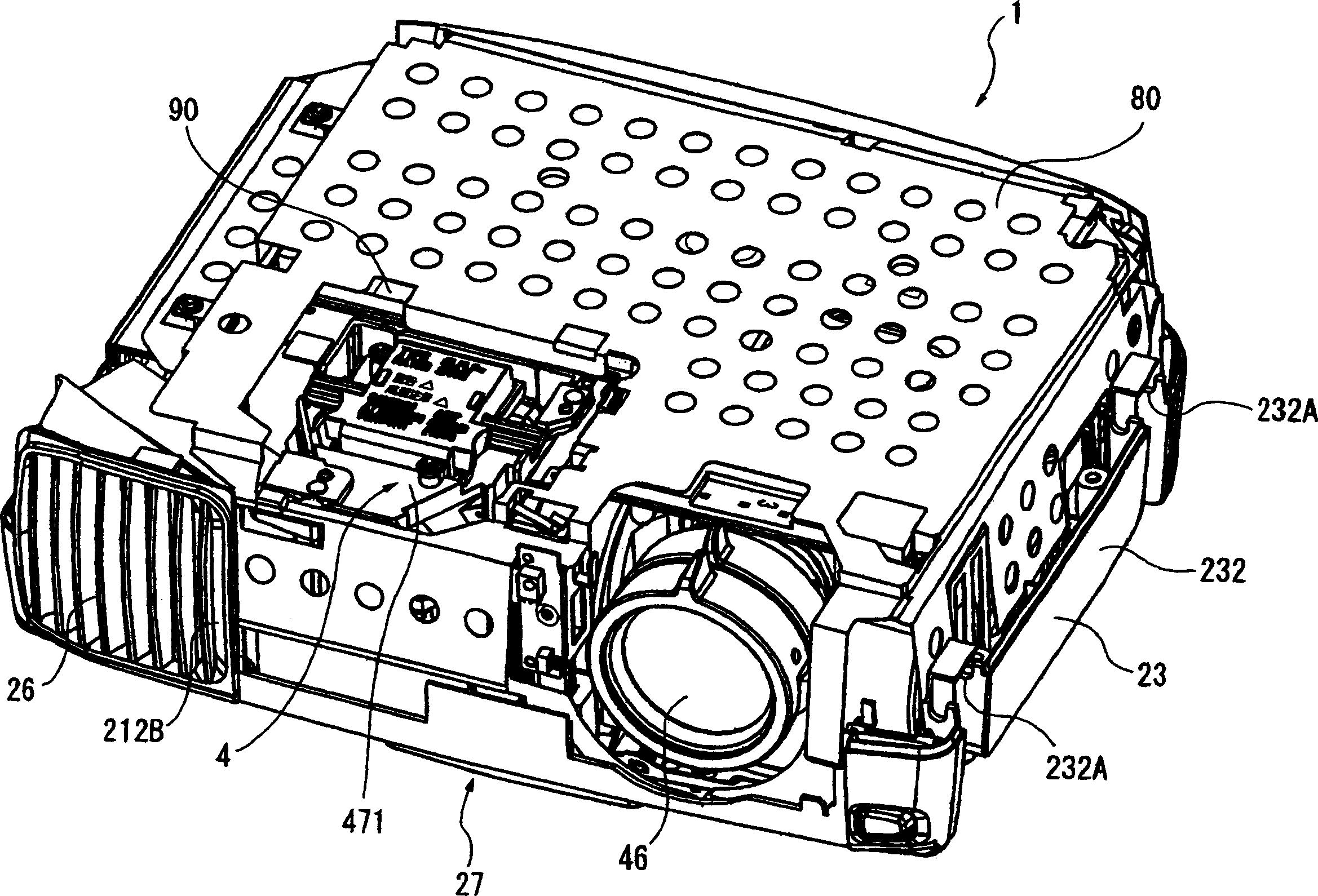
[0182] figure 1 It is an overall perspective view of the projector 1 according to the first embodiment viewed from above, figure 2 It is an overall perspective view of the projector 1 viewed from below. Figure 3 to Figure 5 It is a perspective view showing the inside of the projector 1 . Specifically, image 3 for from figure 1The state unloads the accompanying drawing of the upper box body 21 of projector 1, Figure 4 for from image 3 The drawings observed from the rear after the sealing plate 80, the driving plate 90 and the upper housing 472 are removed, Figure 5 for from Figure 4 The attached state detaches the optical unit 4. The components 4, 21, 80, 90 and 472 constituting the projector will be described below.

[0183] exist Figure 1 to Figure 5 Among them, the projector 1 includes an oute...

no. 2 Embodiment approach

[0295] Next, a second embodiment of the present invention will be described.

[0296] In the following description, the same structure and the same member as those of the above-mentioned first embodiment are given the same reference numerals, and their detailed descriptions are omitted or simplified.

[0297] In the optical device of the first embodiment described above, the holding member 446 is provided with pins 447A protruding from the four corners of the rectangular plate-shaped body 446A. On the other hand, the optical device of the second embodiment is different in that, as shown in FIG. 15 , the holding member 446 has a standing piece 447B having a substantially L-shaped front surface. Other configurations and manufacturing methods are the same as those of the first embodiment.

[0298] Specifically, the upright pieces 447B are located at the four corners of the rectangular plate-shaped body 446A, protrudingly arranged to extend along the edge of the rectangular plate...

no. 3 Embodiment approach

[0303] Next, a third embodiment of the present invention will be described.

[0304] In the following description, the same structures and the same components as those of the first embodiment are given the same reference numerals, and detailed descriptions thereof are omitted or simplified.

[0305] In the optical device of the first embodiment described above, the holding member 446 is provided with the pins 447A protruding from the four corners of the rectangular plate-shaped body 446A. On the other hand, the optical device of the third embodiment is different in that, as shown in FIG. 16 , a holding member 446 is provided with a standing piece 447C having a substantially L-shaped front surface. Other configurations and manufacturing methods are the same as those of the first embodiment.

[0306]Specifically, the upright piece 447C is located on the four corners of the rectangular plate-shaped body 446A, and protrudes along the end edge of the rectangular plate-shaped body ...


PUM


Abstract

The present invention provides an optical device that achieves reduction in size, reduction in manufacturing costs, improved image quality, and so forth, by simplification and the like of a panel in prisms (POP) structure wherein light-modulating devices and a color synthesizing optical element are integrally formed. A POP structure is configured wherein pins integrally formed with a holding member are inserted through holes formed in the four corners of holding frames storing the liquid crystal panelsso as to fix the holding frames and holding members by adhesion. End faces of holding members opposite to the pins are fixed by adhesion to the side faces of bases fixed on the upper and lower faces of a cross-dichroic prism.

Description

[0001] The present invention relates to an optical device that integrates a dimming device that modulates colored light based on image information, and a color synthesis optical element that synthesizes the colored light modulated by the dimming device, a method for manufacturing the optical device, and an optical device using the optical device. projector. Background technique [0002] In the past, the light beam emitted from the light source was separated into three primary colors of red, green, and blue light by a color separation optical system such as a dichroic mirror, and at the same time, each color light was adjusted according to image information by three dimming devices such as a liquid crystal panel. Modulation is performed, and the modulated light of each color is synthesized by a cross dichroic prism, and a color image is magnified and projected through a projection lens, that is, a three-plate projector is known. [0003] In such projectors, each dimming device ...

Claims


Application Information

Patent Timeline
Patent Type & Authority Applications(China)
IPC IPC(8): G02F1/13G02B27/18G02F1/00G02F1/01G02F1/1333G02F1/1335G03B21/00G03B21/14G03B33/12H04N5/74H04N9/31
CPCG03B21/00H04N9/3144H04N9/3105G03B21/14G03B21/005G03B21/145A47K13/24E03D9/08H01H37/52H01H83/20
Inventor 北林雅志渡边信男藤森基行柳泽佳幸上原太介桥爪俊明
Owner SEIKO EPSON CORP
Why Eureka
Try Eureka