
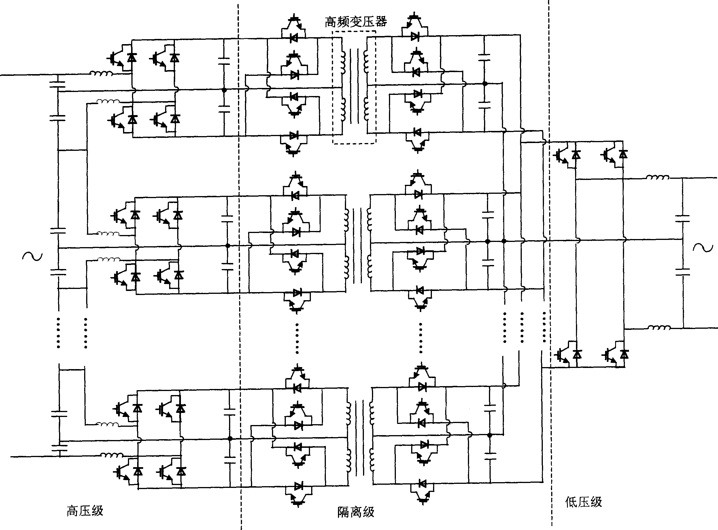
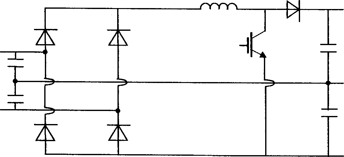
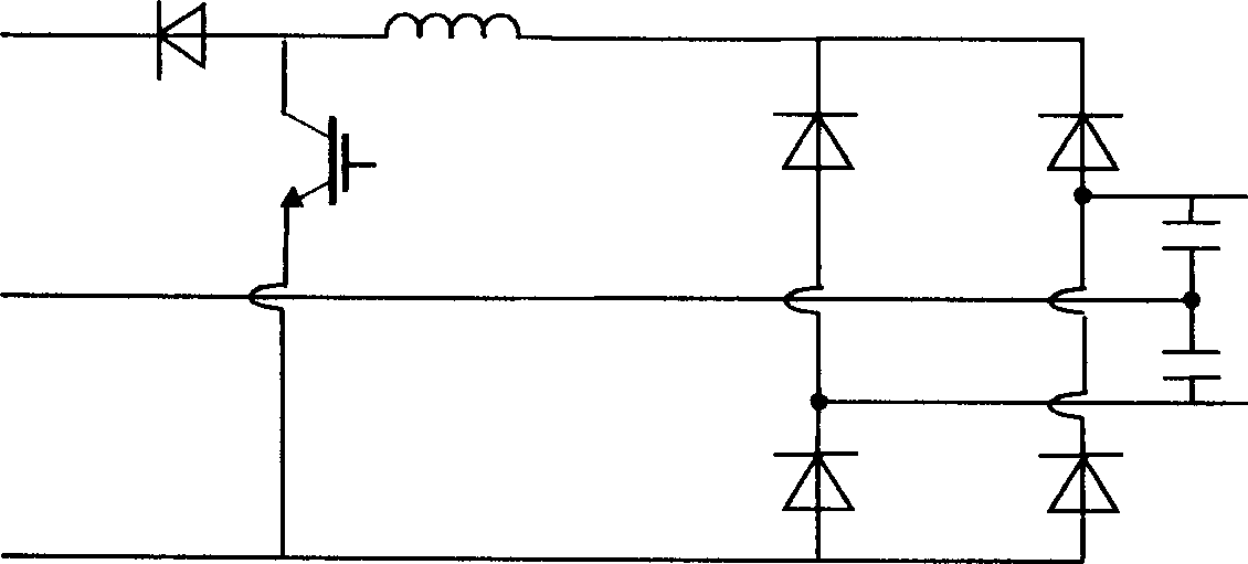
Electric power electronic transformer

A technology of power electronics and transformers, which is applied in the field of voltage conversion devices, can solve problems such as bidirectional power flow and low-voltage level current sharing, and achieve the effects of reducing input and output current harmonics, reducing the number of switching devices, and reducing costs

Inactive Publication Date: 2003-03-12
HUAZHONG UNIV OF SCI & TECH
View PDF0 Cites 45 Cited by
  • Summary
  • Abstract
  • Description
  • Claims
  • Application Information

AI Technical Summary

Problems solved by technology

[0015] The invention proposes a power electronic transformer, which aims to simplify the circuit structure, save switching devices, and solve the problems of bidirectional power flow and low-voltage level current sharing

Method used


Image

  • Electric power electronic transformer
  • Electric power electronic transformer
  • Electric power electronic transformer

Examples


example 1

[0034] Example 1: 100kVA, 6300V / 380V, step-down transformer,

[0035] The high-voltage stage of each phase of the transformer is composed of 12-stage power conversion modules, and each module is composed of two 1200V / 105A two-unit IGBT (Insulated Gate Bipolar Transistor) modules; It is composed of corresponding series of power conversion modules, and each module is also composed of two 1200V / 105A two-unit IGBT modules. Through this stage, the DC voltage is modulated into a high-frequency square wave of 6k Hz; the high-frequency transformer of each phase is pressed 40kVA, designed with a switching frequency of 6k Hz, the part of the isolation stage close to the low-voltage stage is the reduction part, which is composed of four 1200V / 400A one-unit IGBT modules. Through this stage, the high-frequency square wave is restored to DC voltage; the low-voltage stage module It also consists of four 1200V / 400A one-unit IGBT modules.

[0036] Example 2: 100kVA, 380V / 10000V, step-up trans...


PUM


Abstract

The invention relates to a voltage conversion device in the electronic power system in order to simplify the loop structure, save switch devices and solve the issues of bidirectional flow of the power as well as the equal flows in the low voltage stages. The device includes 1-4 phases. Each phase is independent with the identifical structure composed of the high voltage stage, the isolation stage and the low voltage stage. The high voltage stage includes 2-30 identical power conversion modules in serial. The isolation stage includes the part of the modulation / demodulation in high frequncies etc. The low voltage stage includes the power conversion module. Comparing with the foreign scheme, the number of the devices is reduced one-third, and the cost also is reduced.

Description

technical field [0001] The invention relates to a voltage conversion device of a power system, especially a voltage conversion device of 10KV or below in a power distribution system. Background technique [0002] The power transformer is the most basic component of the power system and plays a very important role in the power transmission system. At present, the voltage conversion device in the power system usually adopts an iron-core oil-immersed power transformer. It has the advantages of simple structure, high reliability and low manufacturing cost. However, it also has the following disadvantages: [0003] 1. The transformer is large in size and heavy in weight. The mineral oil used in the transformer will bring environmental problems and it is not easy to maintain; [0004] 2. The secondary side voltage of the transformer cannot be kept constant. As the load increases, its secondary side voltage will drop; [0005] 3. Due to the nonlinear characteristics of ferroma...

Claims


Application Information

Patent Timeline
Patent Type & Authority Applications(China)
IPC IPC(8): H02M5/00H02M5/44
Inventor 毛承雄陆继明范澍方华亮
Owner HUAZHONG UNIV OF SCI & TECH
Learn More