Magnetic yoke for electromagnetic clutch

A technology of electromagnetic clutches and yokes, applied in clutches, magnetic drive clutches, non-mechanical drive clutches, etc., can solve the problem of high installation costs

Inactive Publication Date: 2003-03-19
SANDEN CORP
View PDF0 Cites 3 Cited by
  • Summary
  • Abstract
  • Description
  • Claims
  • Application Information

AI Technical Summary

Problems solved by technology

Therefore, this common method of connecting the terminal portion of the external wire and the coil requires multiple steps for installation, which has a disadvantage of high installation cost
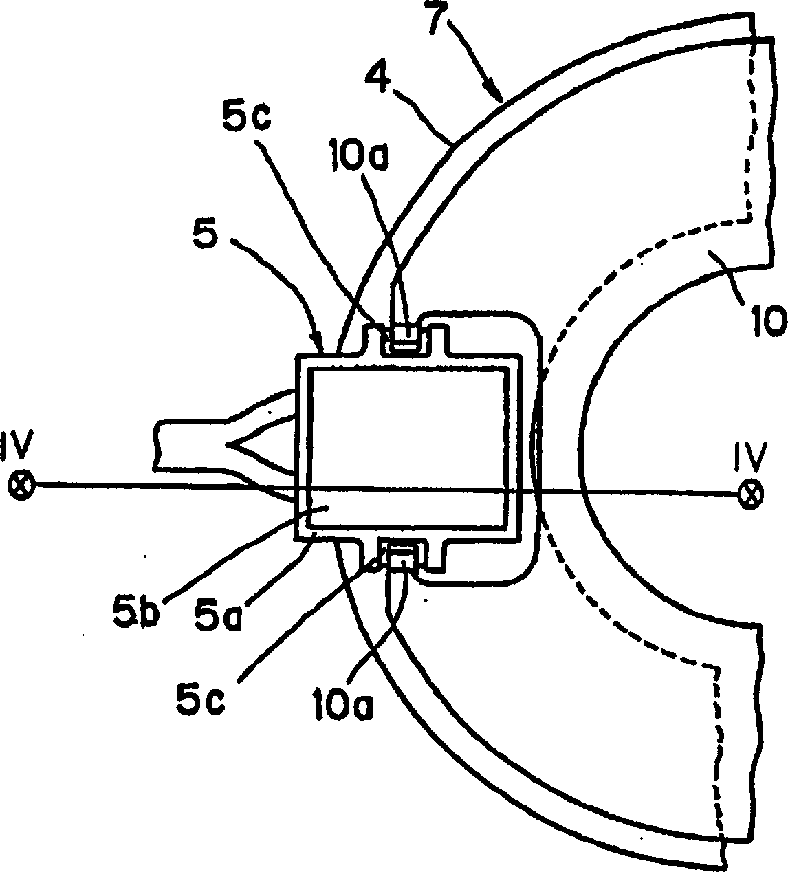
[0008] Therefore, there is room for improvement in the electrical connection structure of the external wires 6a, 6b in the connector 5 of the yoke 7 and the terminal portions 2a, 2b of the coil 2.

Method used


Image

  • Magnetic yoke for electromagnetic clutch
  • Magnetic yoke for electromagnetic clutch
  • Magnetic yoke for electromagnetic clutch

Examples


Embodiment Construction

[0029] FIG. 5(a) is an exploded perspective view of the connection structure of the external wires 6a, 6b and the terminal portions 2a, 2b (not shown) of the coil 2 of the present invention. The main element of the invention is a pair of contact elements 11 . The contact element 11 is in the shape of a rectangular parallelepiped including an upper plate 11a, a pair of first side plates 11f, 11f opposed to each other, and a pair of second side plates 11c, 11c opposed to each other. The interior of the contact element 11 is hollow, and there is no bottom plate opposite the upper plate 11a.

[0030] A slit 11g cut from the bottom side of the contact member 11 is provided on each of the pair of first side plates 11f, 11f. On each of the pair of second side plates 11c, 11c, slits 11d, 11e cut out from the bottom side of the contact member 11 are provided.

[0031] Diode 12 has leads 12a and 12b.

[0032] Two circular grooves 5g, 5g for accommodating external wires 6a, 6b are pro...


PUM


Abstract

A yoke of an electromagnetic clutch includes a ring case, a coil assembly, a connector, and at least one contact. The ring case includes an annular groove and an opening. The coil assembly is positioned in the annular groove. The connector is positioned in the opening of the ring-case and includes a first groove to receive an end portion of the coil assembly, a second groove to receive a lead wire of a diode, and a third groove to receive an end portion of an external wire. The at least one contact includes three pairs of slits and may be inserted in the connector so that each of the three pairs of slits is aligned with a respective one of the first groove, the second groove, and the third groove to form an electrical connection between the end portion of the coil assembly, the lead wire of the diode, and the end portion of the external wire.

Description

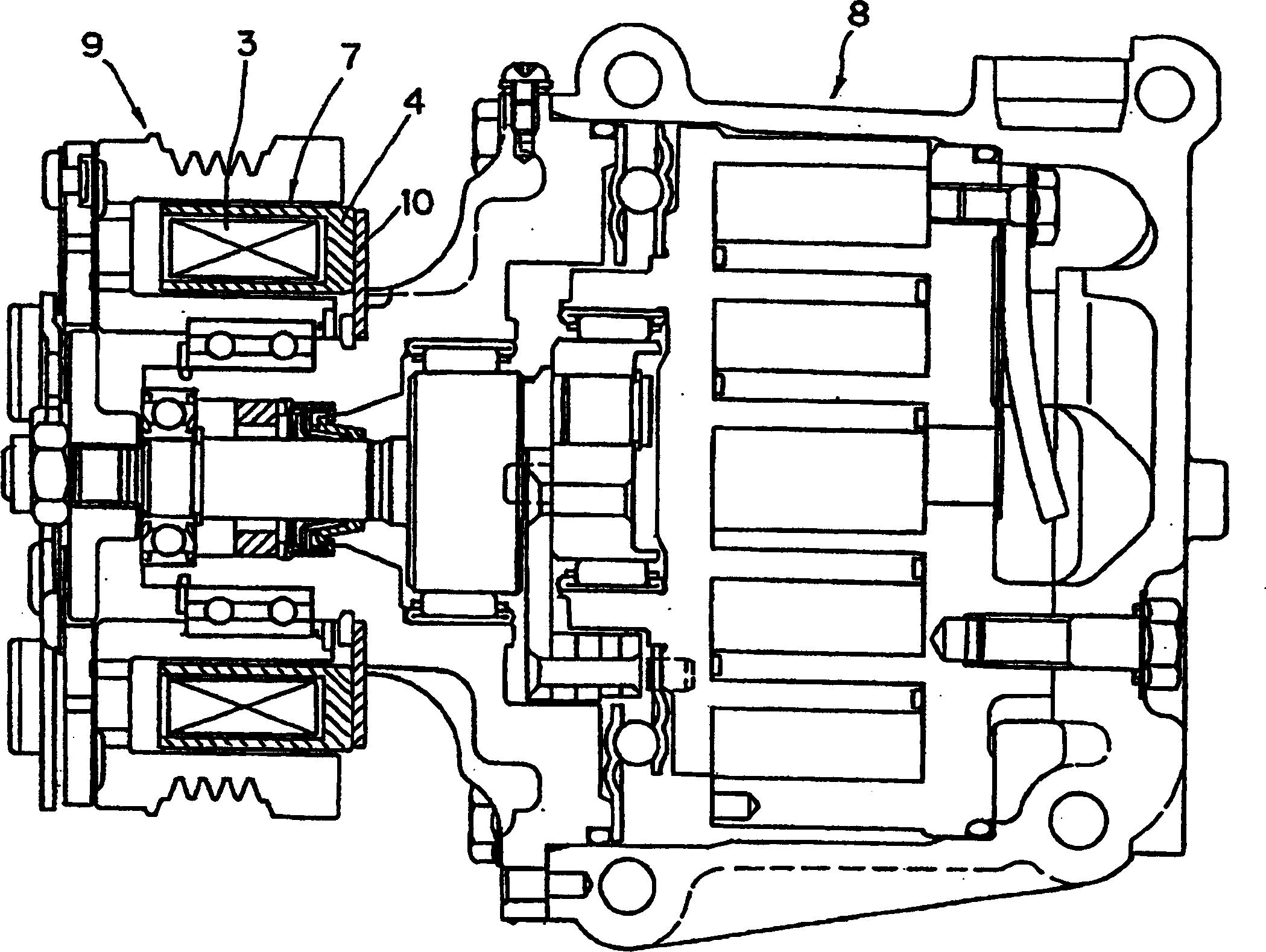
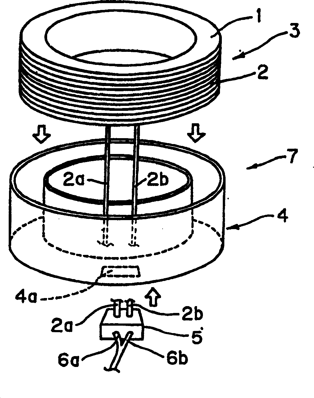
technical field [0001] The invention relates to an electromagnetic clutch. More particularly, the present invention relates to an electrical connection structure in an electromagnetic clutch yoke. Background technique [0002] figure 1 An automotive air conditioner compressor 8 equipped with an electromagnetic clutch 9 is shown. The electromagnetic clutch 9 controls connection / disconnection between the drive source and the drive shaft of the compressor 8 . [0003] The yoke 7 is an important part of the electromagnetic clutch 9 . The yoke 7 includes an annular housing 4 and a coil assembly 3 . The coil assembly 3 is installed in the circular groove of the annular housing 4 . The bottom of the annular casing 4 is fixed on the body of the compressor 8 by a plate 10 . [0004] figure 2 is an exploded perspective view of the yoke 7. The coil assembly 3 includes a coil core 1 and a coil 2 wound on the coil core 1 . The coil 2 has terminal portions 2a, 2b. On a part of ...

Claims


Application Information

Patent Timeline
Patent Type & Authority Applications(China)
IPC IPC(8): F16D27/10F16D27/112H01F27/28H01R4/24H01R9/22
CPCH01R9/226H01F27/2828F16D2027/005F16D2027/001H01R4/2454F16D27/112
Inventor 藤生英明
Owner SANDEN CORP
Why Eureka
Try Eureka