
Grease supplementing apparatus

A technology of grease and grease lubrication, applied in the direction of lubricating oil input, maintenance and safety accessories, bearings, etc., can solve the problems of too little grease, bite, rapid heat generation, etc., and achieve the effect of simple structure

Inactive Publication Date: 2003-03-26
NSK LTD
View PDF0 Cites 23 Cited by
  • Summary
  • Abstract
  • Description
  • Claims
  • Application Information

AI Technical Summary

Problems solved by technology

[0003] When rolling bearings rotate at high speeds and are simultaneously replenished with grease without sufficient control, it may result in excess grease causing rapid heat generation, or may result in too little grease and insufficient bearing lubrication resulting in seizure

Method used


Image

  • Grease supplementing apparatus
  • Grease supplementing apparatus
  • Grease supplementing apparatus

Examples


Embodiment Construction

[0025] Embodiments of the present invention will be described below with reference to the accompanying drawings.

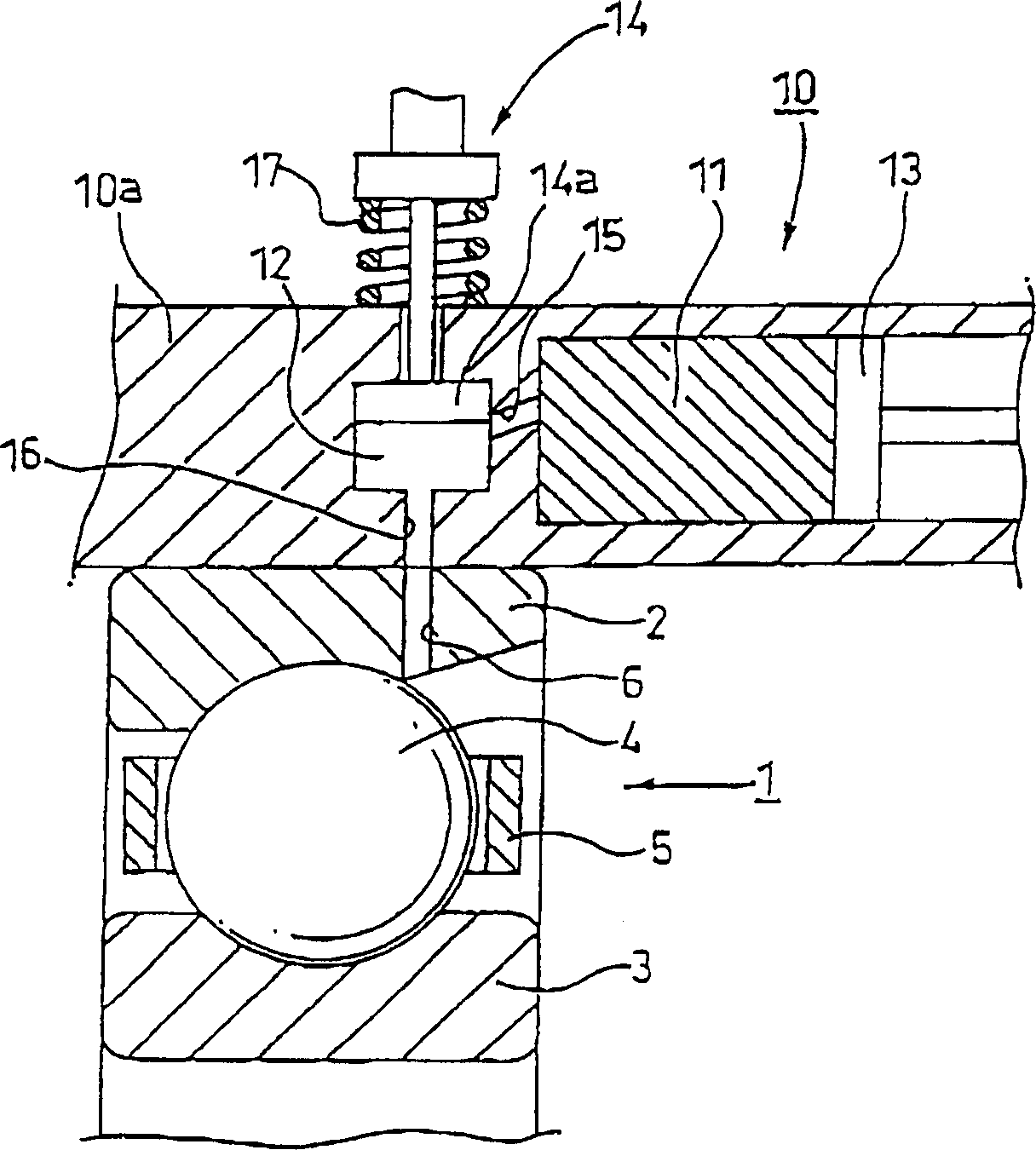
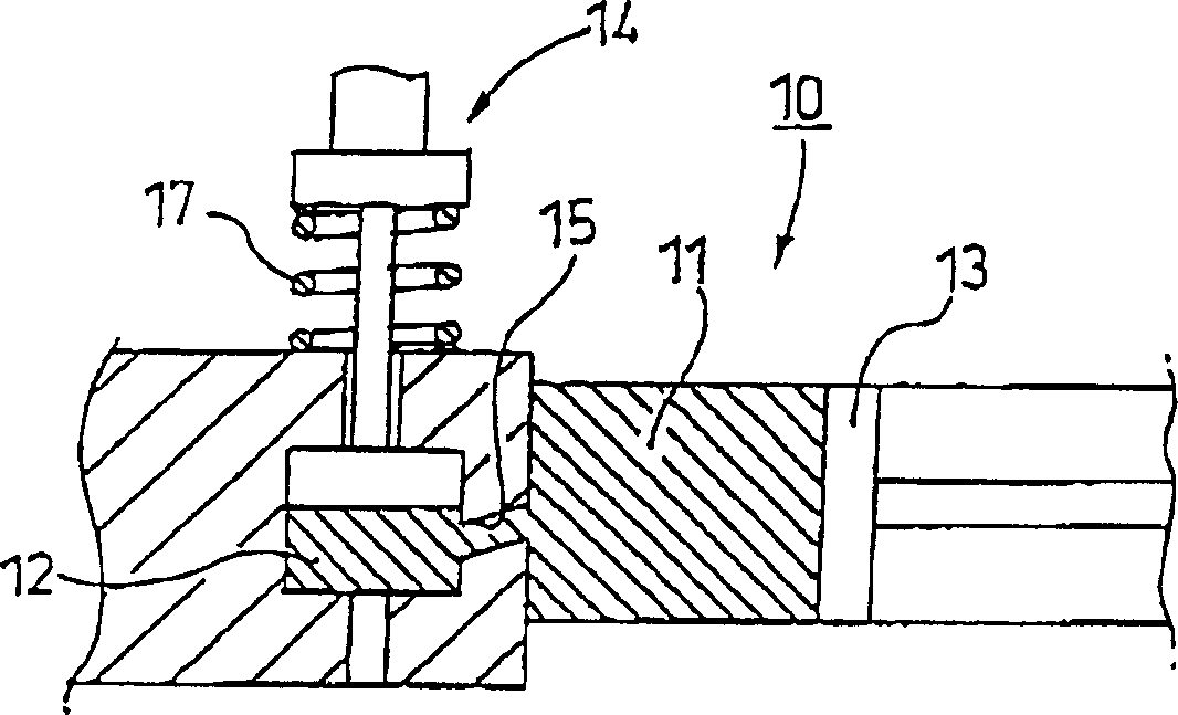
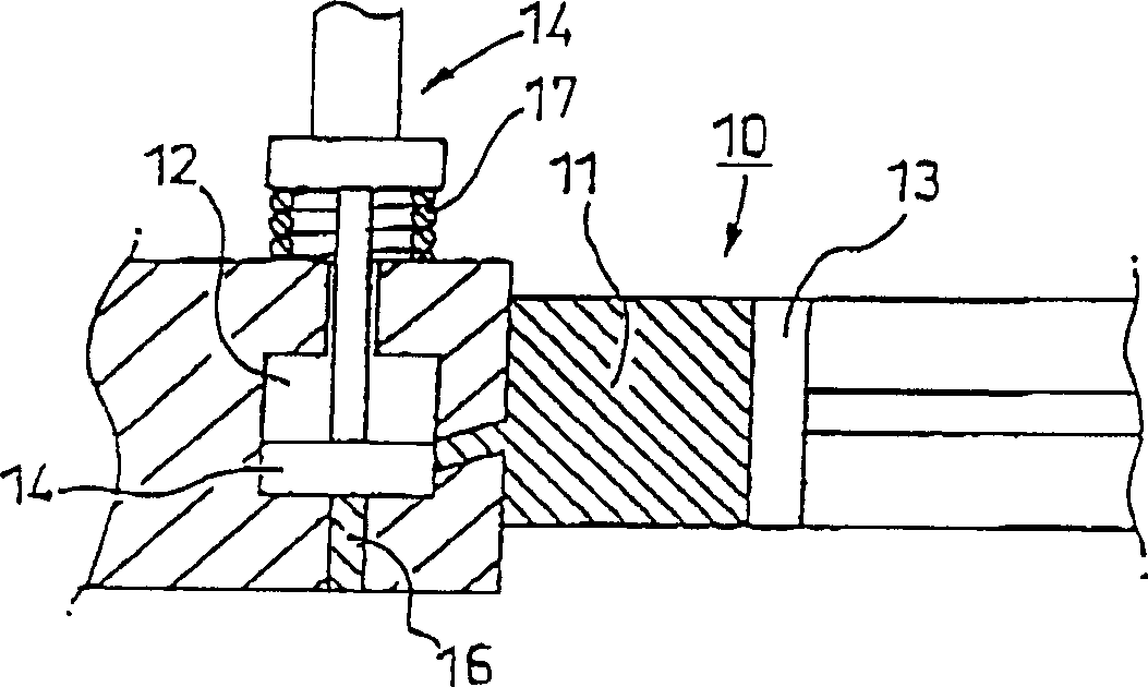
[0026] figure 1 Shown is a cross-sectional view of the grease replenishing device according to the first embodiment of the present invention. A rolling bearing (ball bearing) 1 to be replenished with grease generally includes an outer ring 2, an inner ring 3, rolling elements (balls) 4 rotatably sandwiched between the outer ring 2 and the inner ring 3, and a cage 5, which holds A frame rollably holds the rolling elements at regular intervals along the circumference of the rolling bearing.

[0027] The rolling bearing 1 is arranged such that the outer surface of the outer ring 2 fits on the inner surface of the housing 10a. A grease supply hole 6 is formed in the outer ring 2, which communicates with the inside of the rolling bearing and opens to the inner surface of the outer ring, so that the grease supplied by the grease replenishing device 10 can flow into th...


PUM


Abstract

A grease replenishing device replenishes a grease-lubricated rolling bearing with a grease. The grease replenishing device has a storage chamber portion and a pressing member. The storage chamber portion stores the grease. The pressing member pushes the grease out of the storage chamber into an interior of the rolling bearing.

Description

technical field [0001] The present invention relates to a grease replenishing device for replenishing grease to a grease-lubricated rolling device, which supports a high-speed rotating main shaft and the like. Background technique [0002] At present, there are many machines that can be used to replenish grease for low-speed rotating rolling bearings to prolong the life of the bearings. However, little or no machinery has been used in practice to control the amount of grease delivered to rolling bearings rotating at high speeds. [0003] When rolling bearings rotate at high speeds without sufficient control while replenishing grease, there may be too much grease causing rapid heat generation, or too little grease so that the bearings are under-lubricated and cause seizure. Contents of the invention [0004] The present invention was made under these circumstances. The object of the present invention is to provide a grease replenishing device which normally replenishes a ...

Claims


Application Information

Patent Timeline
Patent Type & Authority Applications(China)
IPC IPC(8): B23Q11/12F16C33/58F16C33/66F16N11/08F16N11/10F16N37/00
CPCF16C33/6622F16N37/003F16C19/163F16C33/6607
Inventor 西端伸司森田康司高野晋
Owner NSK LTD
Learn More