Sheet glass manufacturing apparatus

A technology for producing equipment and glass, applied in glass manufacturing equipment, glass forming, glass forming, etc., can solve problems such as inability to form

Inactive Publication Date: 2003-04-02
EGLASS铂金技术有限公司 +1
View PDF0 Cites 12 Cited by
  • Summary
  • Abstract
  • Description
  • Claims
  • Application Information

AI Technical Summary

Problems solved by technology

Therefore, the base material used for flat panel displays or information recording media is a special glass with a high crystallization temperature, so the production equipment using the original overflow fusion method will not be able to form

Method used


Image

  • Sheet glass manufacturing apparatus
  • Sheet glass manufacturing apparatus
  • Sheet glass manufacturing apparatus

Examples


Embodiment Construction

[0017]

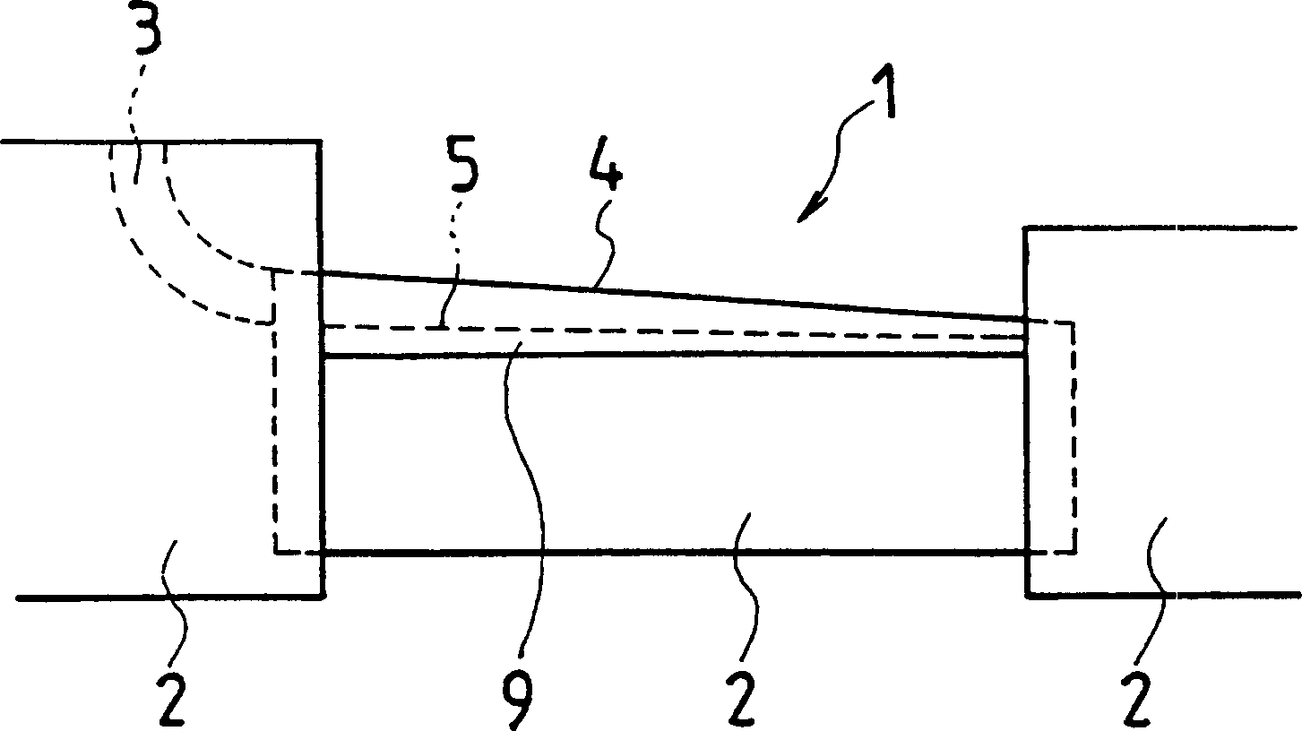
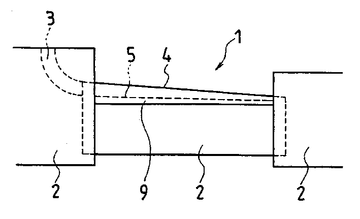
As shown in the figure, the forming body is composed of the following parts: a body 1 with a wedge-shaped cross-section and converging downward; side members 2 and 2 for adjusting the width of the glass plate are arranged on both sides of the body 1; Glass inlet 3. Although omitted in the drawing, the introduction port 3 is connected to a melting furnace containing clarified molten glass, and conveys the molten glass from the melting furnace into the groove portion 5 of the body 1 .

[0018]

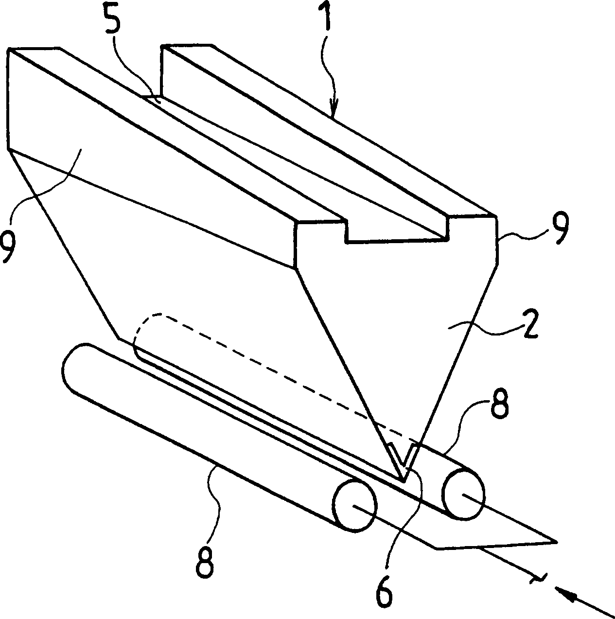
exist figure 1 , the molten glass is conveyed to the groove portion 5 and flows from left to right along the groove portion 5 while overflowing from the upper edge 4 . The overflowing molten glass G flows down along the two surfaces 9 of the body 1, as figure 2 As shown, and integrated at the lower end edge to form a glass plate GR. The glass plate GR is pulled downward by a roller table (not shown) so that the glass plate GR moves downward, thereby achieving the purpose of ...


PUM


Abstract

The invention provides an apparatus, such as non alkaline glass applied to sheet glass for a display substrate of a liquid crystal display, having a high devitrification temperature. A cooling member 8 is disposed at a heating source 6 of side end members 2 and the downflow glass temperature of an inner layer verging on the heating source 6 is kept at the devitrification temperature of this glass or above and the outside surface temperature of the downflow glass is kept below the devitrification temperature of the glass.

Description

[0001] technical field The invention relates to the production equipment of thin plate glass, especially a kind of production equipment of thin plate glass with high crystallization temperature. [0002] Background technique As a production process of high-quality thin plate glass, there was originally a production method called "overflow fusion method". [0003] The overflow fusion method is to make the molten glass flow down along the two surfaces of a forming body with a wedge-shaped cross-section and converge downwards, and merge into one body just below the lower edge of the forming body, and then make it gradually cool At the same time, it is drawn downward to form a thin plate glass. [0004] In this forming method, once the glass merges just below the lower end edge of the forming body having a wedge-shaped cross section, the forming process is immediately terminated, so that it cannot be deformed thereafter. If the viscosity of the glass in the vicinity of ...

Claims


Application Information

Patent Timeline
IPC IPC(8): C03B17/06
CPCC03B17/064
Inventor 酒本修中尾秦昌上堀徹埃伯哈特·斯考茨米罗斯拉夫·莫拉夫斯基迈克尔·巩特尔
Owner EGLASS铂金技术有限公司
Why Eureka
Try Eureka