Pattern evaluating apparatus, pattern evaluating method and program

An evaluation method and technology for evaluating devices, which are applied in measurement devices, optical devices, image enhancement, etc., can solve the problems of changing the detection result of the size of the pattern, increasing the workload of the measurer, and the size of the pattern being dependent on the detection magnification.

Inactive Publication Date: 2003-04-16
KK TOSHIBA
View PDF4 Cites 12 Cited by
  • Summary
  • Abstract
  • Description
  • Claims
  • Application Information

AI Technical Summary

Problems solved by technology

[0008] However, in the above-mentioned existing methods for detecting contour points of figures, due to the shape or position of figures, the contours cannot be detected or the contours are detected incorrectly.
Moreover, in the above-mentioned existing method, the size of the ROI obtained by decomposing the graphic will also change the detection result of the graphic size
At the same time, in the above-mentioned existing methods, the ROI must be specified, which makes the designation of the ROI require complicated steps when the shape of the measured figure is complex, and the workload of the measurer increases, which even leads to the reliability of automatic detection. reduce
Moreover, in the above existing methods, the contrast / black and white of the measured pattern, or the change of the taper angle on the side of the pattern wall, etc. may cause the change of the result of pattern size detection.
Furthermore, in the above-mentioned conventional method, there is also the problem that the detection result such as the pattern size depends on the detection magnification.

Method used


Image

  • Pattern evaluating apparatus, pattern evaluating method and program
  • Pattern evaluating apparatus, pattern evaluating method and program
  • Pattern evaluating apparatus, pattern evaluating method and program

Examples


no. 1 example

[0039] First, refer to Figure 2 to Figure 10 A first embodiment of the graphic evaluation method of the present invention will be described. In this embodiment, the case of measuring a linear pattern will be described.

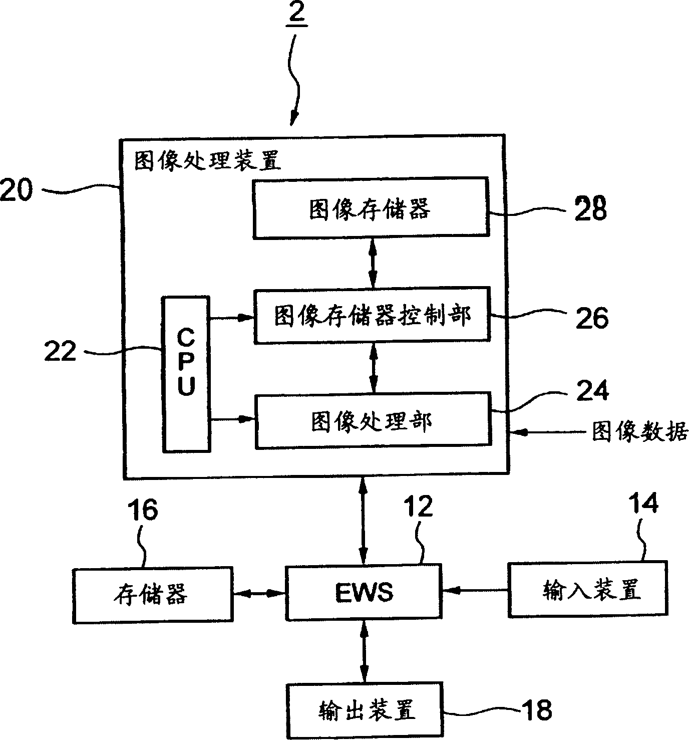
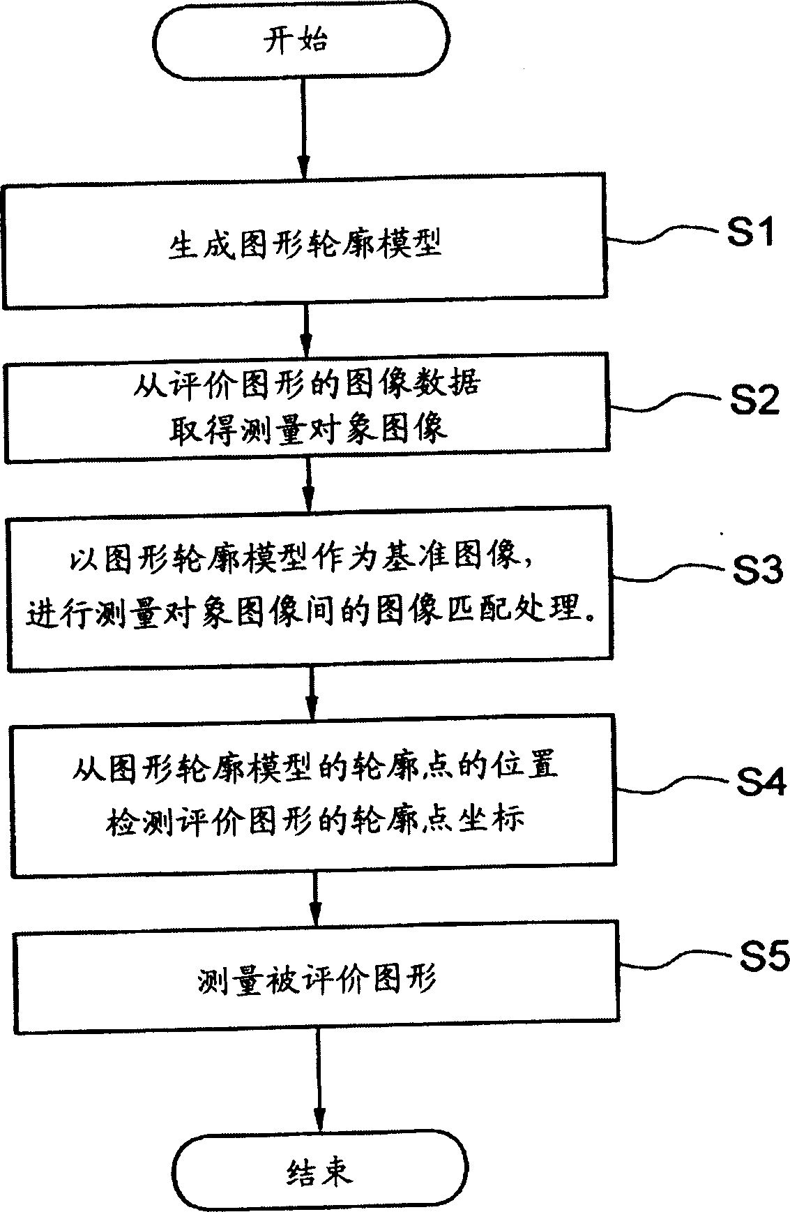
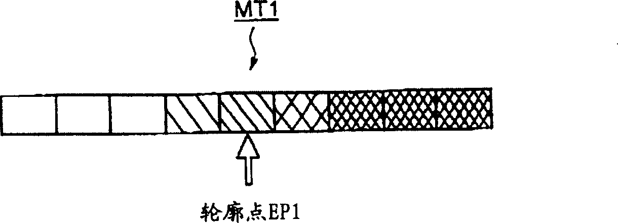
[0040] figure 2 It is a schematic flowchart illustrating the structure of this embodiment. As shown in the figure, first, the contour points of the figure are detected, and the figure contour model is generated in advance (step S1). Figure 3A to Figure 3C is a specific example of the graphic outline model of this embodiment. The graph contour models MT1-MT3 shown in the figure are pixel arrays storing 8-bit density values, and the positions of the contour points EP1-EP3 are also defined for each model. Here, each contour point of the graph contour model is defined as a contour point detected when the graph to be evaluated is viewed from left to right. The graphic contour model is actually stored as data in the image memory 28 of the image processing devic...

no. 2 Embodiment

[0056] Second, refer to Figure 11A and Figure 11B A second embodiment of the pattern evaluation method in the present invention will be described. In this embodiment, the case of detecting the closed curve contour of a circular figure will be described.

[0057] As the figure outline model, it is conceivable to use the same model as that of the above-mentioned first embodiment. The case of a closed curve is different from that of a linear graph, and the contour points are distributed in all directions. Therefore, measurement cannot be performed only with the scanning direction of the reference image fixed horizontally. Such as Figure 11A As shown, the reference image scanning is performed on the X-direction DS1, DS2, and the Y-direction DS3, DS4 of the circular figure P4, thereby detecting contour points in all directions. Additionally, if Figure 11B As shown, the same as the first embodiment (referring to Fig. 5B), first detect the center of the circular figure P4, ...


PUM


Abstract

A pattern evaluation system which receives image data of a pattern to be evaluated to evaluate the pattern includes an edge model producing part which produces a pattern edge model and an edge point coordinate detecting part which carries out an image matching processing to an image of the pattern with the pattern edge model to detect coordinates of an edge point of the pattern.

Description

[0001] Cross References to Related Applications [0002] This application claims the benefit of priority of Japanese Patent Application No. 2001-294209 filed on September 26, 2001 based on 35 USC $119; the contents of which are incorporated herein by reference. technical field [0003] The present invention relates to a pattern evaluation device, evaluation method and program for pattern size and shape measurement. Background technique [0004] A conventional pattern evaluation method will be described by taking a specific example of an evaluation method for a fine pattern of a semiconductor. [0005] The evaluation of patterns is very important in the manufacturing process of semiconductors, especially for fine patterns formed by photolithography and etching processes. Conventionally, the evaluation method of CDSEM (Critical Dimension Scanning Electron Microscope) using electron beams is generally used to evaluate the size of patterns (for example, the line width of linear...

Claims


Application Information

Patent Timeline
Patent Type & Authority Applications(China)
IPC IPC(8): G06T5/00G06T7/00G06T7/60
CPCG06T7/602G06T7/0004G06T7/0083G06T2207/10056G06T2207/30148G06T7/12G06T7/62
Inventor 三井正
Owner KK TOSHIBA
Why Eureka
Try Eureka