Power transmitting device

A technology of power transmission device and driving force, which is applied in the direction of power device, air pressure power device, transmission device control, etc. It can solve the problems of engine stall, vehicle acceleration, drop, etc., and achieve the effect of preventing engine stall

Inactive Publication Date: 2003-04-23
HONDA MOTOR CO LTD
View PDF1 Cites 55 Cited by
  • Summary
  • Abstract
  • Description
  • Claims
  • Application Information

AI Technical Summary

Problems solved by technology

For this reason, in the power transmission device that transmits the engine output to the wheels, if the same power transmission control is performed during partial cylinder operation as in all cylinder operation, the engine load during partial cylinder operation becomes too large, There is such a problem that the engine stalls or the acceleration performance of the vehicle decreases

Method used


Image

  • Power transmitting device
  • Power transmitting device
  • Power transmitting device

Examples


Embodiment Construction

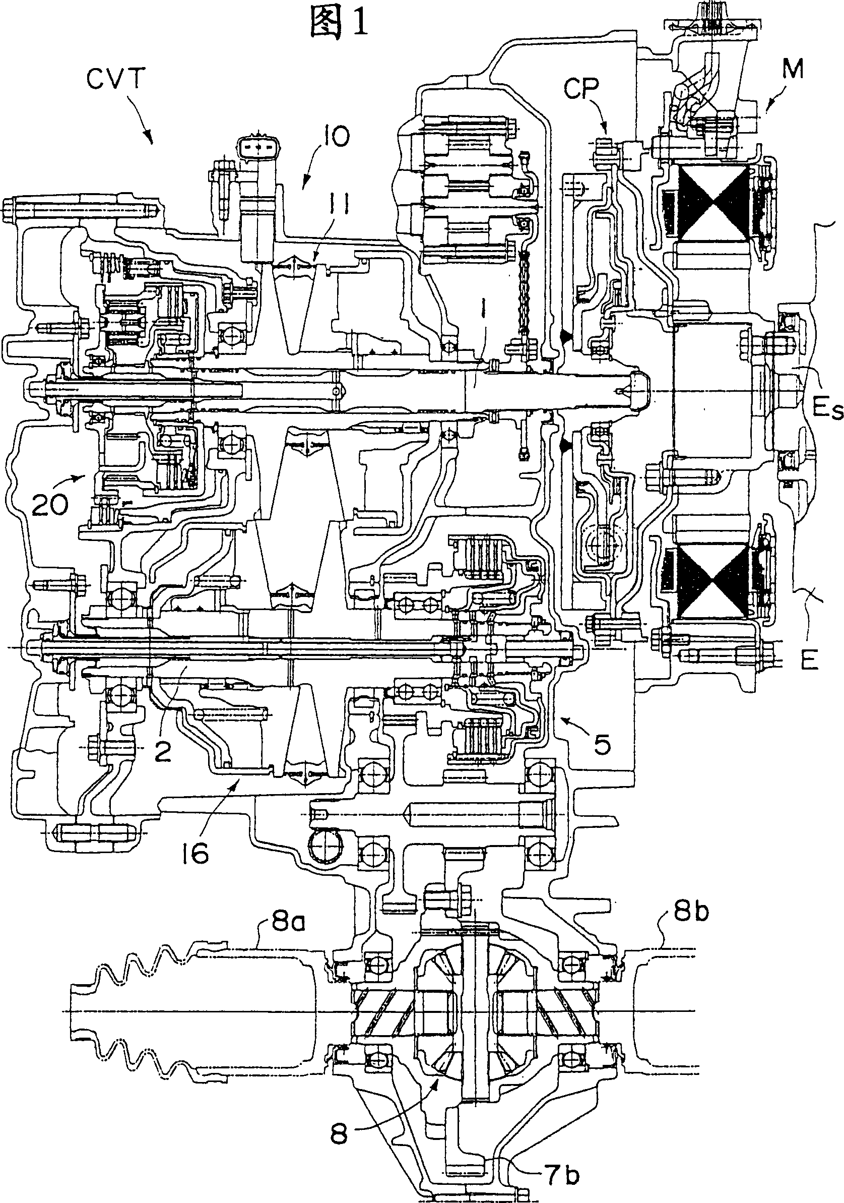
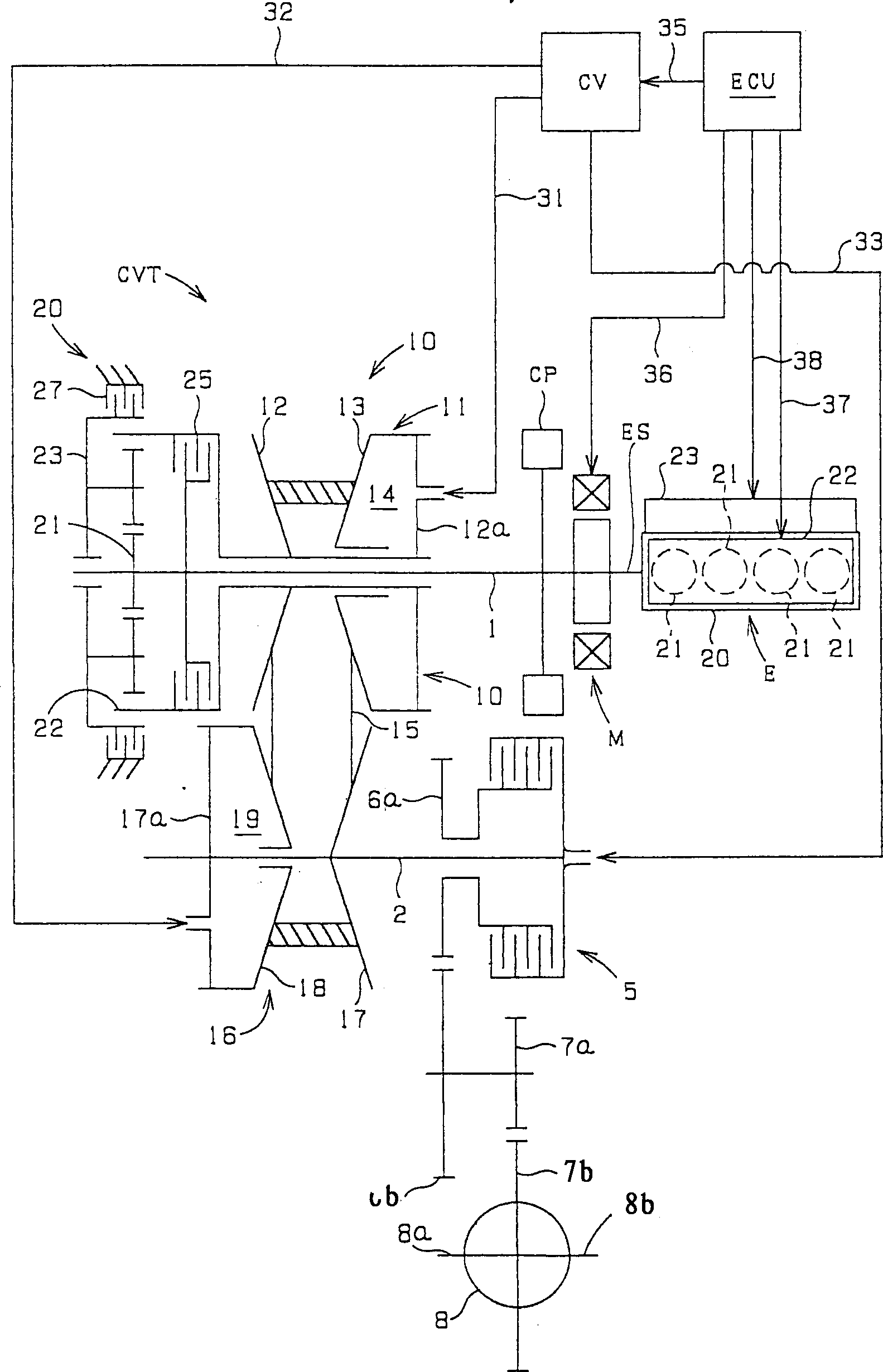
[0013] Next, preferred embodiments of the present invention will be described with reference to the drawings. FIG. 1 shows a sectional view of a power transmission device for a vehicle according to an embodiment of the present invention, figure 2 The configuration of the power transmission system of the device is shown. As can be seen from these two figures, the power transmission device is composed of an engine E, a motor generator M arranged on the engine output shaft Es of the engine E, and a continuously variable transmission CVT connected to the engine output shaft Es by a connection mechanism CP.

[0014] The engine E is a four-cylinder reciprocating engine, and pistons are respectively arranged in four cylinder chambers 21 formed in the cylinder block 20 . This engine E has an intake and exhaust control device 22 for controlling the operation of the intake and exhaust valves for intake and exhaust of each cylinder chamber 21, and a device for performing fuel injection ...


PUM


Abstract

A power transmission comprises a continuously variable transmission CVT, which transmits a rotational driving force from an engine E, a starting clutch 5, which variably sets the transmission capacity for the continuously variable transmission CVT, and a control valve CV, which controls the engagement operation of the starting clutch 5. While the engine E is in a partial cylinder operation mode, the control valve CV controls the engagement operation of the starting clutch 5 to attain a predetermined transmission capacity at a rotational speed of the engine that is higher than for a case of the engine in an all cylinder operation mode.

Description

technical field [0001] The present invention relates to a power transmission device configured to transmit the driving force of an engine composed of a plurality of cylinders to wheels through a driving force transmitter (such as a transmission). A power transmission device of a friction engagement type friction engagement member (for example, a starting clutch) that sets the transmission capacity of driving force. Background technique [0002] Such power transmission devices are often used in automobiles. Recently, idling stop control that stops engine operation when the vehicle is stopped and control that stops several cylinders under predetermined operating conditions to perform engine operation are performed to improve fuel efficiency. For example, Japanese Patent Application Laid-Open No. Sho 59-13154 discloses a transmission control device having a variable-cylinder engine, in which control to increase the transmission ratio is performed during operation of some cylind...

Claims


Application Information

Patent Timeline
Patent Type & Authority Applications(China)
IPC IPC(8): B60W10/04B60K6/405B60K6/485B60K6/543B60W10/02B60W10/06B60W10/10B60W10/101B60W10/107B60W20/00F02D17/02F02D29/00F16D48/02F16D48/06F16H59/76F16H61/02F16H61/66F16H61/662F16H63/50
CPCY02T10/6226F16H59/76F16D48/06B60W10/107B60K6/485B60W10/02B60K6/543B60W2710/027F16H2312/02B60K6/405B60W20/00F16D2500/1045F16D2500/1088F16D2500/306F16D2500/3108F16D2500/5045F16D2500/50858F16D2500/5114F16D2500/7027F16D2500/70605Y02T10/62B60W30/18063B60W20/40
Inventor 山口正明江口高弘
Owner HONDA MOTOR CO LTD
Why Eureka
Try Eureka