High efficient valve assembly for compressor

A technology of valve components and compressors, applied in the direction of engine components, components of pumping devices for elastic fluids, control valves, etc., which can solve problems such as changes and deterioration of compressor efficiency

Inactive Publication Date: 2003-04-23
SAMSUNG GWANGJU ELECTRONICS CO LTD
View PDF0 Cites 3 Cited by
  • Summary
  • Abstract
  • Description
  • Claims
  • Application Information

AI Technical Summary

Problems solved by technology

However, in these methods, since the discharge valve is only provided at one end, it is difficult to correctly position the discharge valve when assembling the valve assembl

Method used


Image

  • High efficient valve assembly for compressor
  • High efficient valve assembly for compressor
  • High efficient valve assembly for compressor

Examples


Embodiment Construction

[0017] Preferred embodiments of the present invention will be described in detail below with reference to the accompanying drawings. exist figure 1 In , the same related elements are denoted by the same reference numerals.

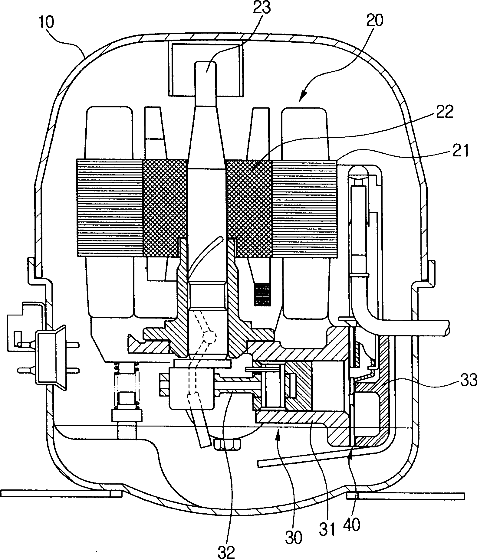
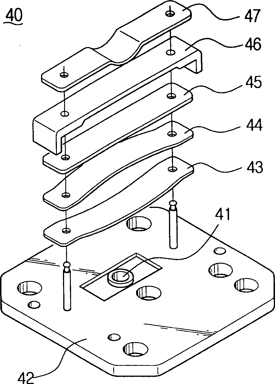
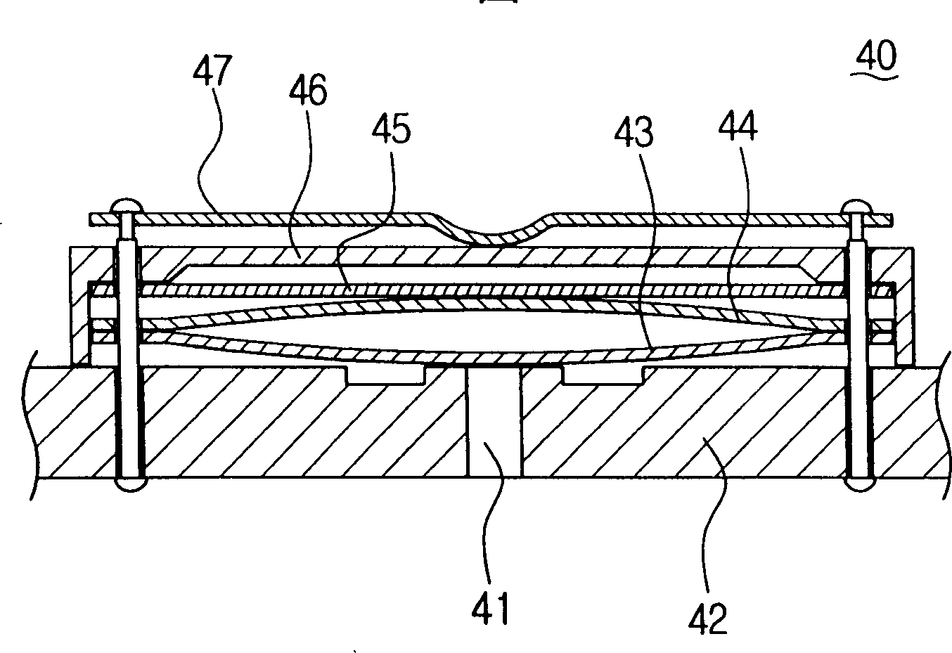
[0018] Referring to Fig. 4, the high-efficiency valve assembly 100 of the present invention comprises: a valve plate 110 with a refrigerant suction hole 111, and first and second discharge valves 112, 112'; figure 1 ) between the suction valve plate 120 of the suction valve 121 to open and close the refrigerant suction hole 111; a discharge valve 130 arranged between the valve plate 110 and the cylinder head 33 to open and close the discharge valve 112, 112' ; a brake valve 140, arranged on the top of the discharge valve 130, so as to control the opening degree of the discharge valve 130; correct position; a retainer 160 for flexibly supporting and setting the detent 150; and discharge valve setting members 132, 152 for positioning the discharge valve 13...


PUM


Abstract

A high efficient valve assembly of a compressor has a valve plate having more than one discharging valve; a discharging valve for opening and closing the discharging valve, one end of the discharging valve is settled at the valve plate between the valve plate and a cylinder head; a stopper for controlling the discharging valve to be placed at a right position, both ends of the stopper are settled at the valve plate at an upper part of the discharging valve; a rivet for settling the discharging valve and the stopper at the valve plate; and settlement units for positioning the discharging valve at the valve plate at the right position and supporting the discharging valve. According to the present invention, the high efficient valve assembly has the discharging settlement units capable of settling the discharging valve of which only one end is supported and supporting the discharging valve, thus the assemble of the valve assembly can be easily done. Furthermore, the position of the discharging valve is not changed afterwards, and power is less consumed since the operation delay of the discharging valve is minimized.

Description

technical field [0001] The present invention relates to a high-efficiency valve assembly for a compressor, and more particularly to a valve assembly for a high-efficiency compressor that reduces refrigerant discharge load by reducing the operating time of the discharge valve and reducing the pressure of the entire compressor. Background technique [0002] Generally, a compressor converts mechanical energy into compressive energy of a fluid being compressed. The compressor draws refrigerant from a low-pressure evaporator to compress the refrigerant in a freezer, such as a refrigerator, and pressurize the refrigerant to a condensing pressure. The compressors include reciprocating compressors, rotary compressors and turbo compressors. [0003] figure 1 Indicates a reciprocating hermetic compressor among many traditional compressors. Generally, a reciprocating hermetic compressor includes: a motor 20 including a rotor 22 and a stator 21 provided in a casing 10; The refrigera...

Claims


Application Information

Patent Timeline
IPC IPC(8): F04B39/10F16K15/16F16K17/04
CPCF16K15/16F04B39/1073Y10T137/7898Y10T137/7892F04B39/10F16K15/162
Inventor 朴圭昌
Owner SAMSUNG GWANGJU ELECTRONICS CO LTD
Why Eureka
Try Eureka