
Method for mounting scattered raster on X-ray detector

A detector and X-ray technology, applied in the field of X-ray detectors, can solve problems such as quantum efficiency reduction

Inactive Publication Date: 2003-04-30
SIEMENS AG
View PDF1 Cites 7 Cited by
  • Summary
  • Abstract
  • Description
  • Claims
  • Application Information

AI Technical Summary

Problems solved by technology

However this leads to an undesired decrease in the detectable quantum efficiency (DQE) at high LO frequencies

Method used


Image

  • Method for mounting scattered raster on X-ray detector
  • Method for mounting scattered raster on X-ray detector
  • Method for mounting scattered raster on X-ray detector

Examples


Embodiment Construction

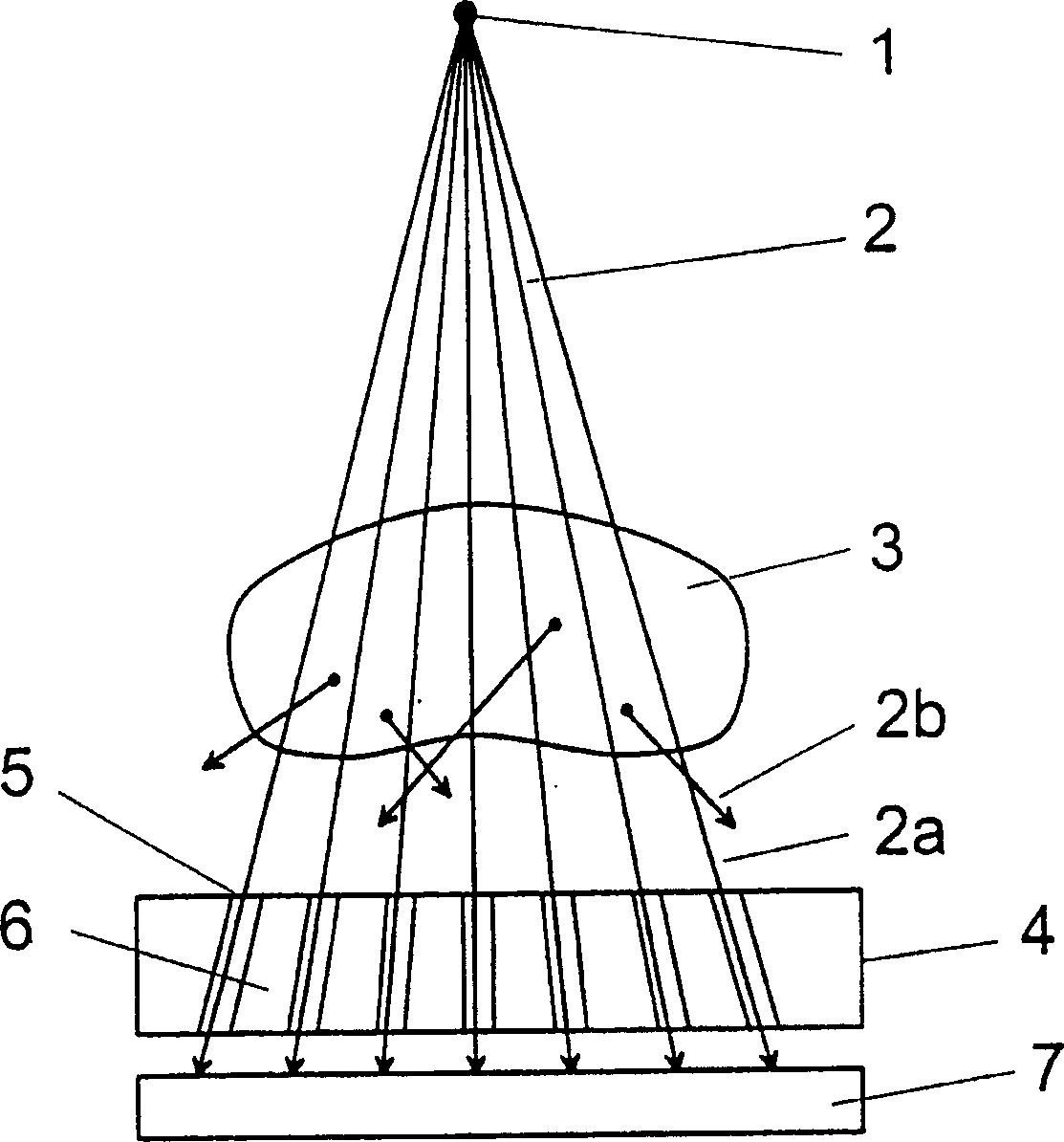
[0033] with the help of figure 1 A typical situation when an object 3 is x-rayed in an x-ray diagnostic apparatus is shown in outline. The object 3 is located between the tube focal point 1 of an x-ray tube and a detector surface 7 . The tube focal point 1 can be regarded as an approximately point-shaped X-ray source. The x-rays 2 emitted by the focal point 1 of the x-ray source travel in a straight line in the direction of the x-ray detector 7 and penetrate the object 3 . The primary ray 2a impinging on the detector surface 7 passes through the object 3 in a straight line after being emitted from the X-ray source 1 , and then provides a locally resolvable distribution of attenuation values ​​of the object 3 on the detector surface 7 . A portion of the x-rays 2 emitted by the x-ray focus 1 is scattered within the object 3 . The resulting scattered radiation 2 b does not contribute to the formation of the desired image information and, when impinging on the detector 7 , sign...


PUM


Abstract

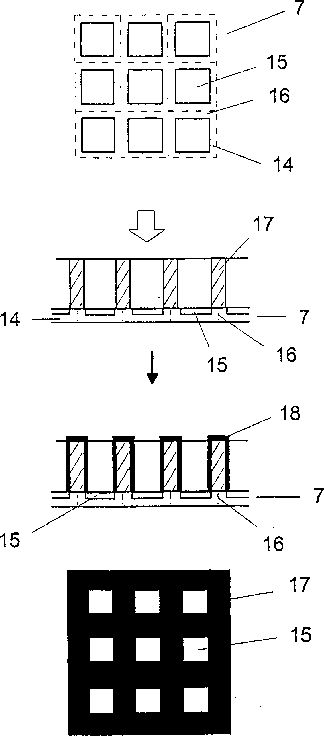
The invention relates to a method for mounting scattered raster on X-ray detector, the detector having a plurality of detector elements (14) arranged in a matrix that form a detector surface having detection regions (15) sensitive to X-rays and less sensitive intermediate regions (16), a basic structure (17) for the stray radiation grid is built up over the detector surface directly on the X-ray detector with a rapid prototyping technique and is subsequently coated or filled with a material that is highly absorbent for X-radiation. An absorbent structure (24) thus arises that lies over the less sensitive intermediate regions (16) of the detector surface. Moire disturbances are avoided in the X-ray image exposure and the detective quantum efficiency (DQE) is increased.

Description

technical field [0001] The invention relates to a method for attaching a scattering grating to an x-ray detector having a plurality of detector elements arranged in a matrix. The invention also relates to an x-ray detector with a scattering grating mounted thereon in this way. Background technique [0002] In today's x-ray imaging technology, high demands are placed on the quality of x-ray imaging images. In this X-ray shooting, especially for X-ray medical diagnosis, an object under inspection is irradiated by X-rays from an approximately point-shaped X-ray source, and the X-rays transmitted through the object under inspection on the opposite side of the X-ray source are measured. The resulting two-dimensional decay distribution. The line-by-line detection of the attenuation of the X-ray beam after it has penetrated the object can also be performed, for example, in a computer tomography apparatus. In addition to X-ray films and gas detectors as X-ray detectors, solid-sta...

Claims


Application Information

Patent Timeline
Patent Type & Authority Applications(China)
IPC IPC(8): G21K1/02
CPCG21K1/025B33Y80/00B33Y40/20
Inventor 马丁·霍埃塞尔哈特穆特·斯克莱比茨
Owner SIEMENS AG
Learn More