Supercharge Your Innovation With Domain-Expert AI Agents!

Suction valve assembly of compressor

A technology for suction valves and compressors, which is applied to parts, pump elements, mechanical equipment, etc. of pumping devices for elastic fluids, and can solve problems such as increasing manufacturing costs

Inactive Publication Date: 2003-05-07
LG ELECTRONICS INC
View PDF0 Cites 0 Cited by
  • Summary
  • Abstract
  • Description
  • Claims
  • Application Information

AI Technical Summary

Problems solved by technology

This leads to the problem of increasing manufacturing cost

Method used


Image

  • Suction valve assembly of compressor
  • Suction valve assembly of compressor
  • Suction valve assembly of compressor

Examples


Embodiment Construction

[0031] Preferred embodiments of the present invention will be described in detail below with reference to examples shown in the accompanying drawings.

[0032] There are several embodiments of the suction valve assembly of the compressor according to the present invention, the most preferred one of which will be described below.

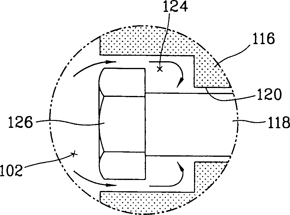
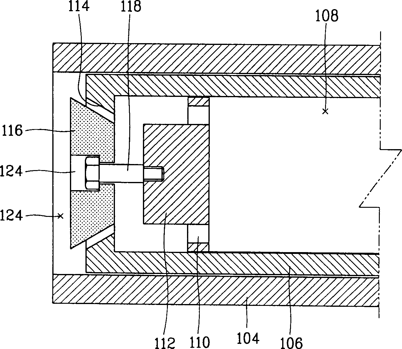
[0033] Figure 4 is a partial sectional view of a compressor employing the suction valve assembly of the present invention, and Figure 5 yes Figure 4 An enlarged schematic of part "B".

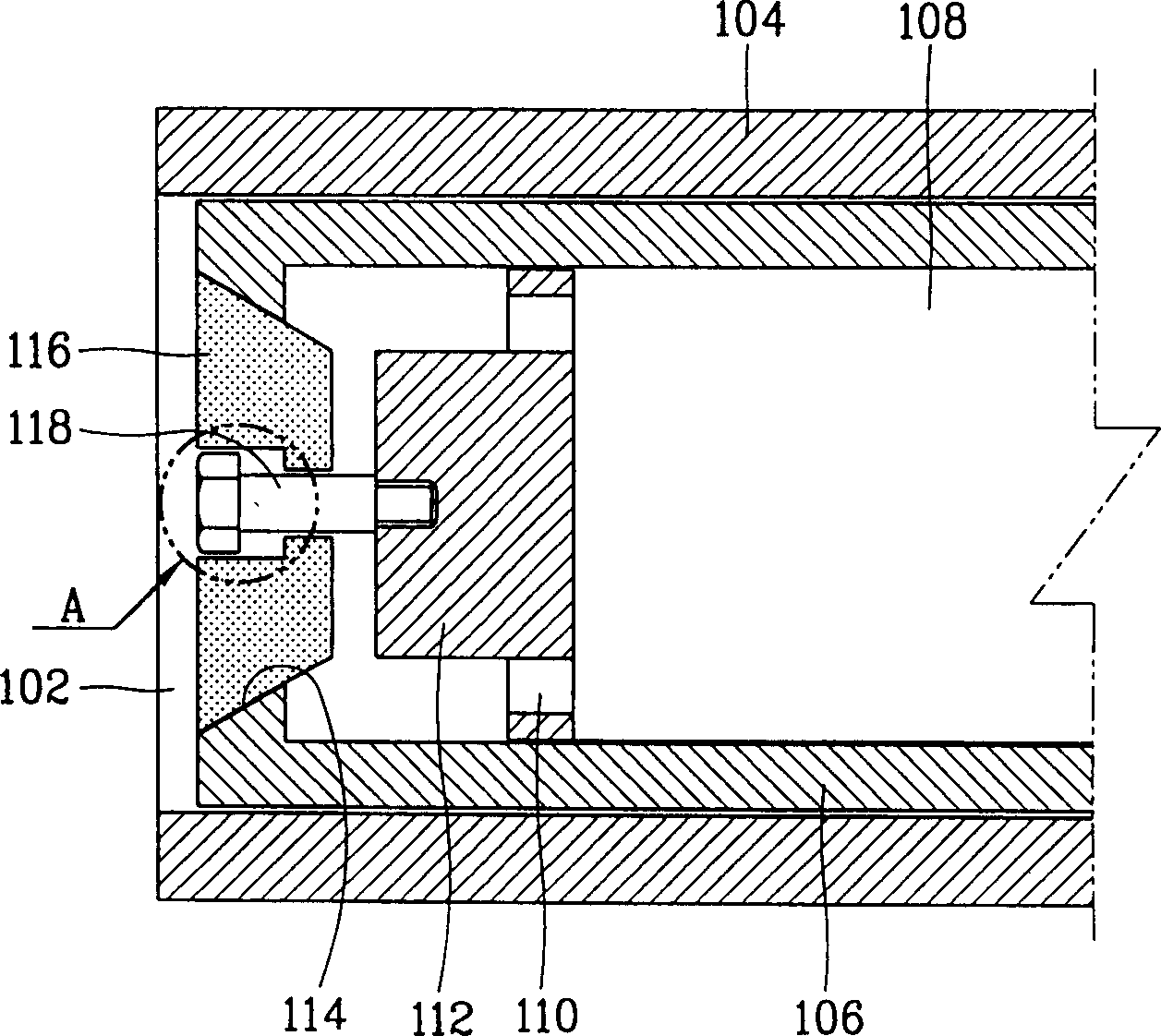
[0034] The compressor of the present invention includes a cylinder 4 fixed at a compressor housing (not shown) and forming a compression chamber 2, a piston 6 arranged to linearly reciprocate in the cylinder 4 to compress fluid and form a suction passage 8 , and a suction valve assembly installed on the front side of the piston 6 and preventing fluid from flowing back from the compression chamber 2 to the suction passage 8 .

[0035] The piston 6 is sealingly r...


PUM


Abstract

A suction valve assembly of a compressor includes: a piston disposed movable in a cylinder forming a compression chamber, having a suction passage for sucking a fluid and a valve seat formed at a front side thereof; a valve body contacted to the valve seat to open and close the fluid, of which a front side making a portion of the compression chamber is formed hermetical; a support rod inserted into a rear portion of the valve body and fixed at one side of the piston and supporting the valve body to be moved in a certain range; and a release preventing unit formed between the valve body and the support rod to prevent the valve body from releasing from the support rod. A guide groove inside a compression chamber is removed to prevent generation of a dead volume, thereby improving an efficiency of a compressor.

Description

technical field [0001] The present invention relates to a suction valve assembly switched by fluid pressure, and more particularly, to a suction valve assembly of a compressor capable of preventing a dead volume from being generated in the compressor. Background technique [0002] Generally, a suction valve assembly is installed between a compression chamber of a compressor etc. in which fluid is compressed and a suction passage for sucking in fluid, so that when fluid is sucked, the suction valve assembly is opened by inertia and the fluid introduced through the suction passage Fluid is supplied to the compression chamber, and when the fluid is compressed, the suction valve assembly prevents fluid compressed in the compression chamber from flowing back into the suction passage. [0003] figure 1 is a partial cross-sectional view of a compressor employing a prior art suction valve assembly, while figure 2 is a schematic diagram showing the operating state of a compressor ...

Claims


Application Information

Patent Timeline
IPC IPC(8): F04B39/10F04B39/00F04B53/12
CPCF04B53/129Y10T137/6086F04B39/0016Y10T137/7918F04B39/10
Inventor 卢基元郑忠旼
Owner LG ELECTRONICS INC
Features
  • R&D
  • Intellectual Property
  • Life Sciences
  • Materials
  • Tech Scout
  • Unparalleled Data Quality
  • Higher Quality Content
  • 60% Fewer Hallucinations
Learn More