Door hinge with covered structure used between door and door frame

A technology for covering structures and door hinges, which is applied in the field of door hinges and can solve problems that are not suitable for residential doors

Inactive Publication Date: 2003-05-14
SIMONSWERK
View PDF2 Cites 21 Cited by
  • Summary
  • Abstract
  • Description
  • Claims
  • Application Information

AI Technical Summary

Problems solved by technology

This known door hinge is only suitable for mounting on light-weight door lea

Method used


Image

  • Door hinge with covered structure used between door and door frame
  • Door hinge with covered structure used between door and door frame
  • Door hinge with covered structure used between door and door frame

Examples


Embodiment Construction

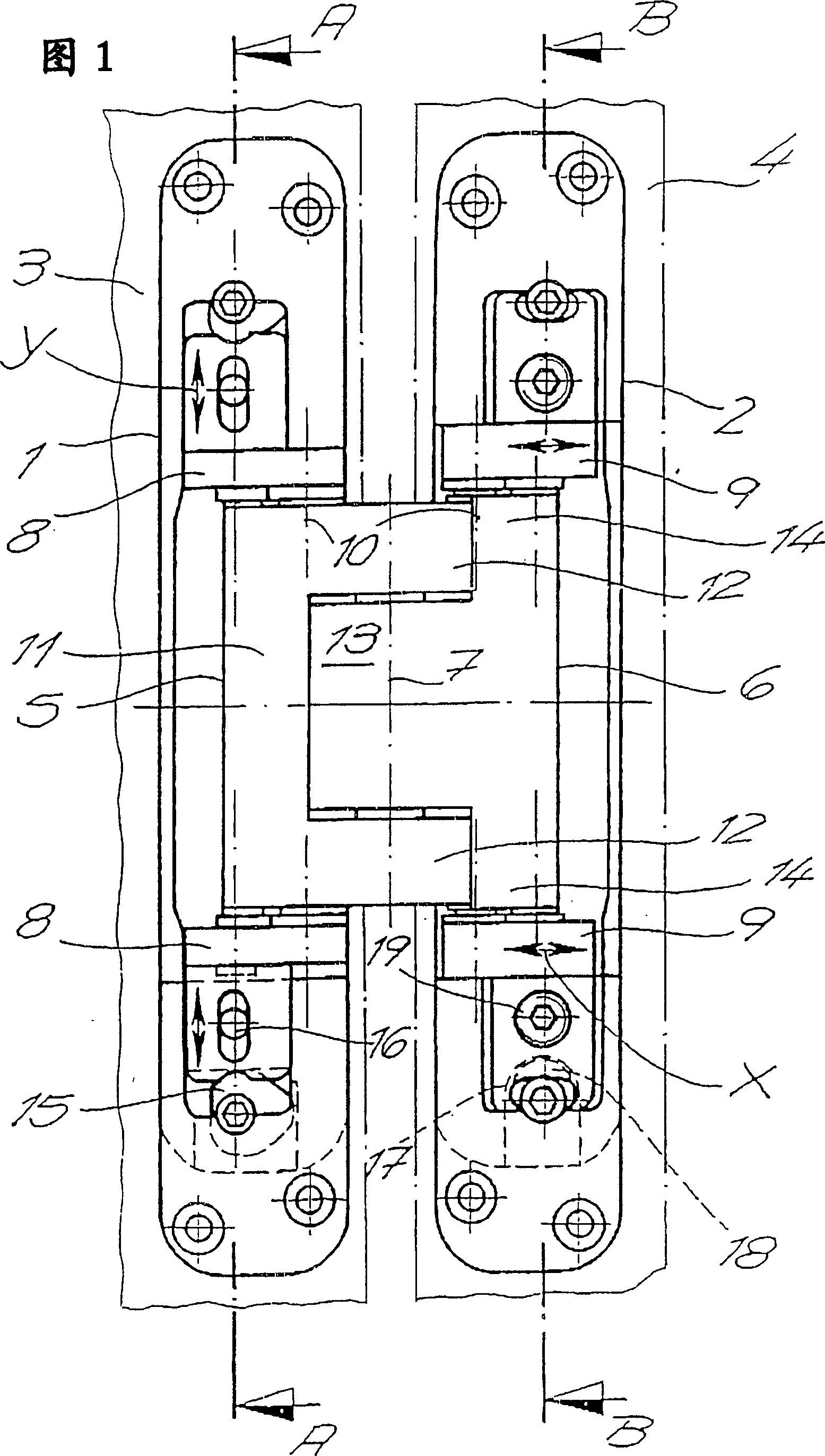
[0025] The door hinge shown is used to pivotally secure the door leaf to the door frame. The door hinges are concealed when the door is closed. It is suitable for heavy doors, especially for house doors, room doors, and house doors.

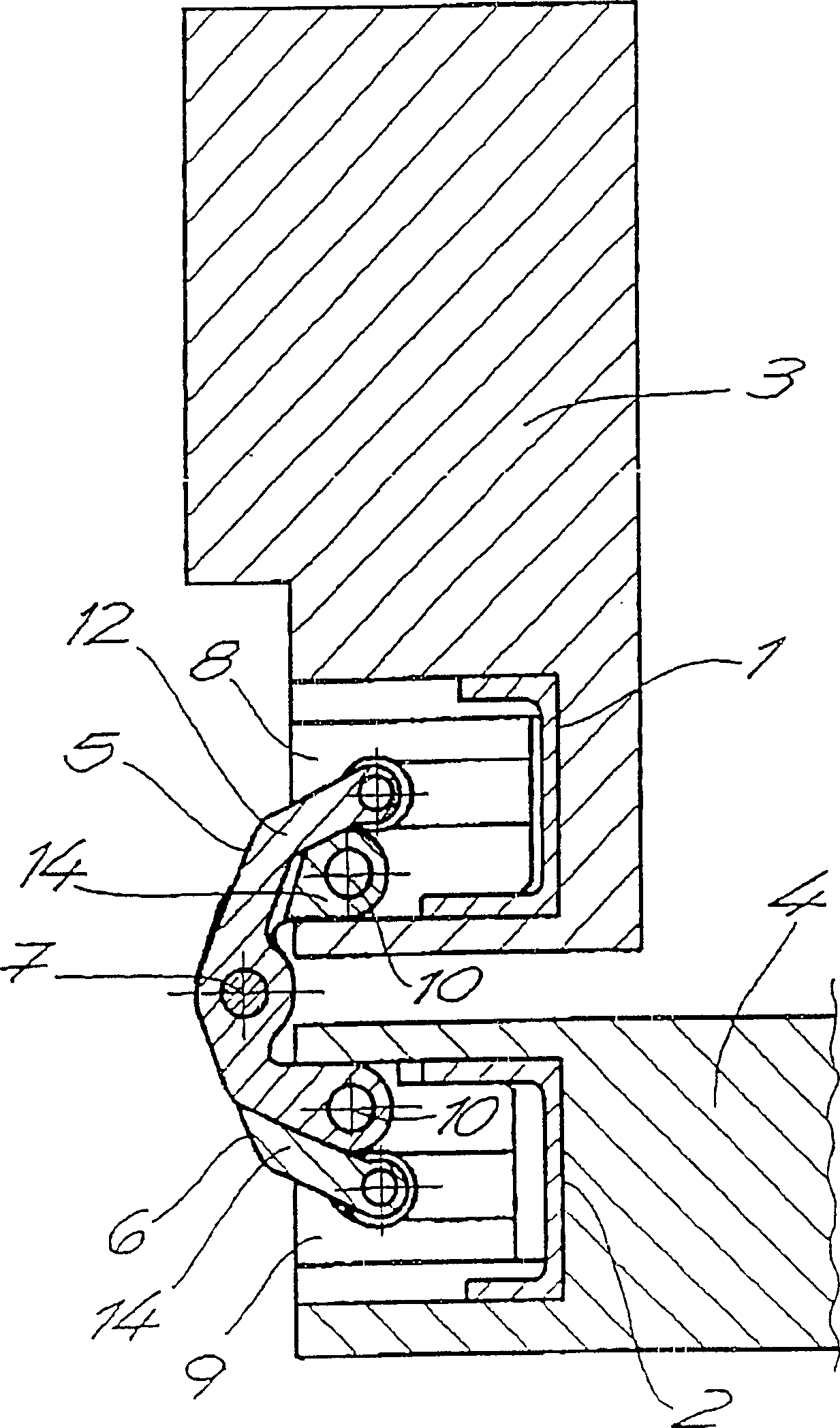
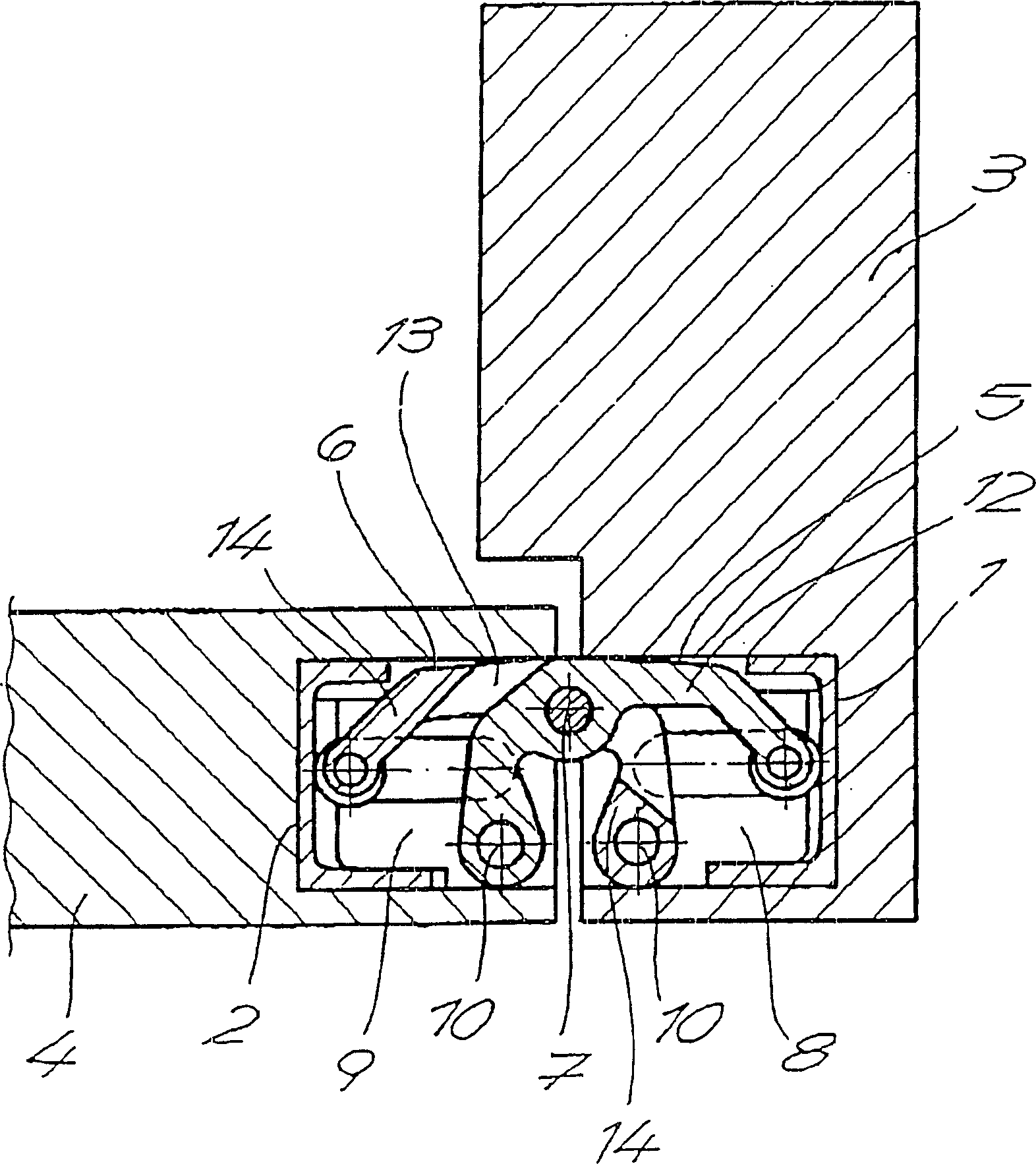
[0026] The basic arrangement of the door hinge shown in the figure includes two receiving bodies 1, 2, two hinge rods 5, 6 and bushings 8, 9 located in the receiving bodies 1, 2, the two receiving bodies 1, 2 can be inserted into a cutout in the door frame 3 as well as in a cutout in the narrow side of the door leaf 4; the two hinged rods 5, 6 are interconnected so as to be pivotable about a vertical axis of rotation 7; in each case one hinged The ends of the rods are mounted on these bushes 8 , 9 to pivot about a vertical axis of rotation 10 , while the ends of the other articulated rod are guided on these bushes 8 , 9 so as to be movable longitudinally. One of the two hinged rods shown in FIG. 1 is formed in a fork shape and has a two-pronged...


PUM


Abstract

The object of the present invention is a door hinge for a covered arrangement between door post and door includes two mounting bases, hinge brackets and adjustable connectors arranged in the mounting bases. The two mounting bases are capable of insertion into recesses in the door post and in the narrow side of the door. The hinge brackets interact in pairs and are connected so as to be capable of pivotal movement about a vertical axis. On each adjustable connector, the end of one hinge bracket is mounted, capable of pivoting about a vertical axis of rotation, and the end of the other hinge bracket is guided for longitudinal movement. One of the two hinge brackets has the form of a fork with two fork arms connecting on a rearward connecting section, wherein the connecting section and the fork arms are mounted at the connectors. The other hinge bracket is inserted in the free space between the fork arms and has a middle element mounted in a rotational manner at the fork arms. The middle element is connected at both ends by broader end segments of the bracket that project upwards and downwards directions. The end segments are mounted on the connectors on the top side and on the bottom side. The hinge brackets extend in the vertical direction over the same height.

Description

field of invention [0001] The invention relates to a door hinge for a covered arrangement between a door frame and a door leaf, having [0002] two receiving bodies, which can be inserted into the cutouts in the door frame and into the cutouts in the narrow sides of the door leaf, [0003] pairs of interacting articulated rods connected to pivot about a vertical axis of rotation, and [0004] A bushing arranged in the housing on which in each case the end of a hinged pin is mounted pivotable about a vertical axis of rotation, while the end of the other hinged rod rests on the bushing Guided above, the end of this other hinged rod is movable both longitudinally and pivotally. [0005] The door frame can be designed as a liner frame, a block frame, or a steel frame. Background technique [0006] A door hinge structure is known from EP1063376A2. With this known design, the hinged rods extend in each case only halfway over the entire vertical portion of the door hinge, where...

Claims


Application Information

Patent Timeline
IPC IPC(8): E05D3/06E05D7/04
CPCE05D7/0415E05D2007/0469E05Y2900/20E05D3/186E05D7/0423E05D2007/0484
Inventor 胡贝特·诺伊克特尔
Owner SIMONSWERK
Why Eureka
Try Eureka