
Electric heat exchanger of air interchanging device

A technology of a ventilation device and an exchanger, which is applied in the field of new electric heat exchangers and achieves the effects of extensive industrial utilization value, extensive utilization value and stable structure

Inactive Publication Date: 2003-05-28
LG ELECTRONICS (TIANJIN) APPLIANCES CO LTD
View PDF0 Cites 4 Cited by
  • Summary
  • Abstract
  • Description
  • Claims
  • Application Information

AI Technical Summary

Problems solved by technology

[0025] This shows that the electric heat exchanger of above-mentioned existing ventilator still has many defectives, and waits to be improved

Method used


Image

  • Electric heat exchanger of air interchanging device
  • Electric heat exchanger of air interchanging device
  • Electric heat exchanger of air interchanging device

Examples


Embodiment Construction

[0050] Below in conjunction with the accompanying drawings and preferred embodiments, the specific implementation, structure, features and effects of the present invention will be described in detail as follows.

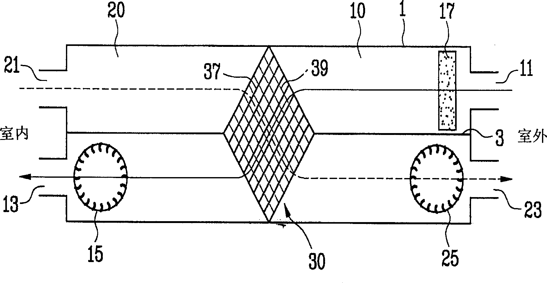
[0051] 1. Square box 10. Air supply pipe

[0052] 11. Air supply inlet 13. Air supply outlet

[0053] 15. Air supply fan 17. Air purification filter

[0054] 20. Exhaust pipe 21. Exhaust suction port

[0055] 23. Exhaust outlet 25. Exhaust fan

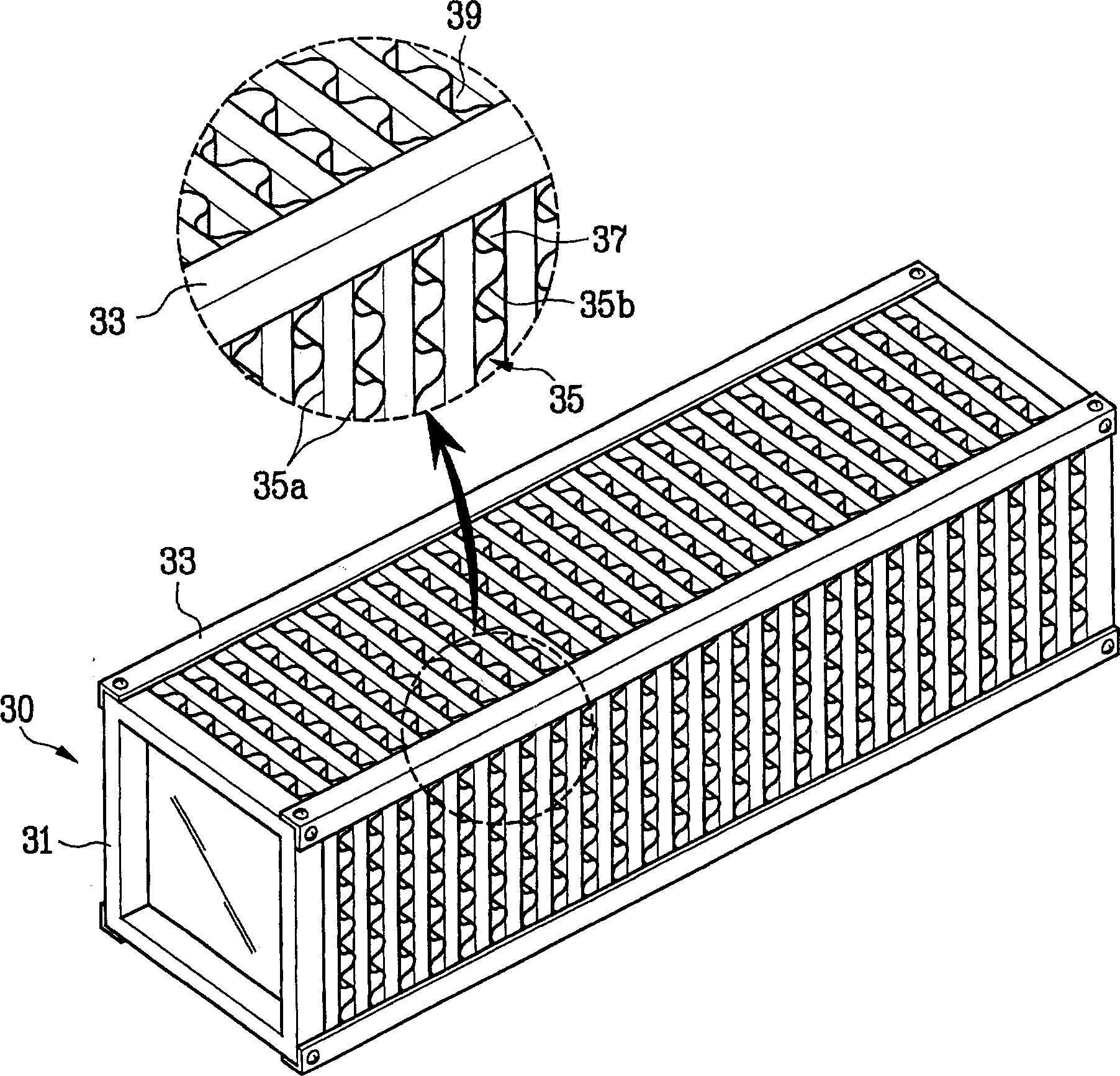
[0056] 3. Separator 30. Electric heat exchanger

[0057] 31. Fixing plate 33. V-shaped fixing strip

[0058] 35. Heat exchange unit 35a. Heat exchange plate

[0059] 35b. Bending plate 37. Air supply channel

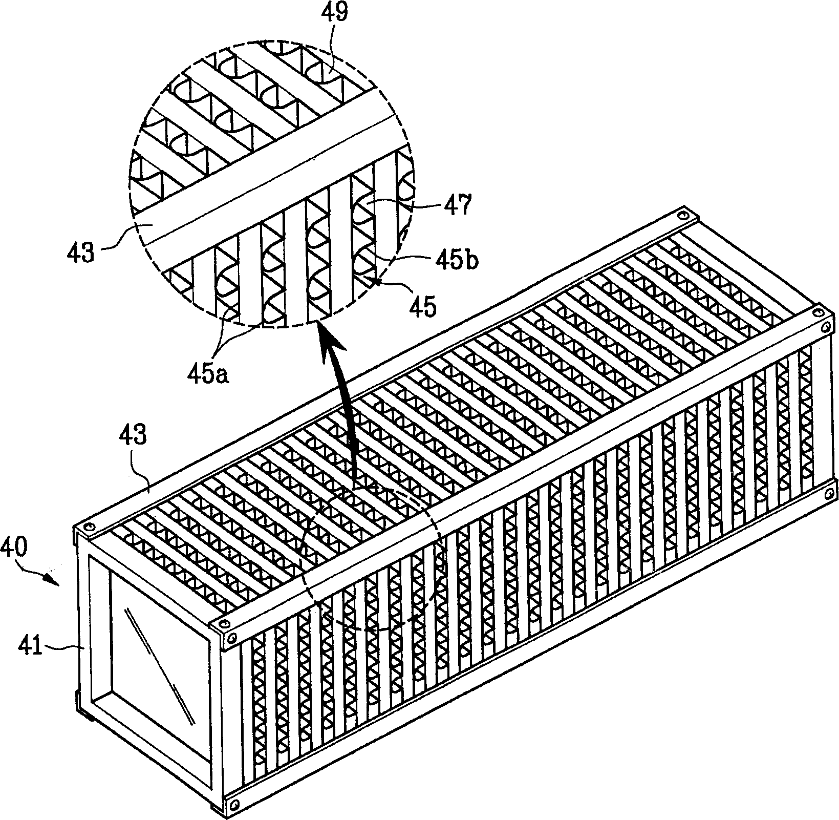
[0060] 39. Exhaust channel 40. Electric heat exchanger

[0061] 41. Fixing plate 43. V fixing bar

[0062] 45. Heat exchange unit 45a. Heat exchange plate

[0063] 45b. Bending plate 45c. Embossed part

[0064] 45d. Friction groove 47. Air supply channel

[0065] 48. Exhaust channel 55b. Bending plate

[006...


PUM


Abstract

An electrothermal exchanger for air exchanger is composed of fixing plates, V-shaped fixing bars, heat exchanging unit consisting of the heat exchanging plates with two side surfaces and bent plates for making air flow monodirectionally, outdoor air supplying channel and indoor air exhausting channel. Its feature is that more friction slots are arranged in said two channels for higher heat exchanging efficiency. Its advantages are simple structure and low cost.

Description

technical field [0001] The invention relates to an electric heat exchanger for a ventilation device, in particular to a novel electric heat exchanger which improves the air channel structure of the electric heat exchanger and improves the heat exchange efficiency between outdoor air and indoor air. Background technique [0002] In a confined space, with the respiration of organisms, the concentration of carbon dioxide increases continuously, and when it reaches a certain concentration, it will affect the respiratory function of organisms. Therefore, when there are many people in a small space such as an office or a bus, it is necessary to frequently exchange indoor polluted air with outdoor fresh air. Air exchange generally adopts a ventilation device. [0003] Most of the traditional ventilation devices use an exhaust fan to force the indoor air out of the room. However, when the exhaust fan forcibly discharges the indoor air, the cold or hot air in the room is discharged...

Claims


Application Information

Patent Timeline
IPC IPC(8): F24F3/147
Inventor 赵敏喆李光元申修沇
Owner LG ELECTRONICS (TIANJIN) APPLIANCES CO LTD
Learn More