
Vacuum cleaner having suction fan

A technology for vacuum cleaners and suction fans, which is applied to vacuum cleaners, cleaning equipment, household appliances, etc. It can solve problems such as the impact of dust collection performance, increased gas flow resistance, and increased flow resistance, so as to improve dust collection performance and suppress forced Effect of heating and promoting cooling

Inactive Publication Date: 2003-07-02
LG ELECTRONICS (TIANJIN) APPLIANCES CO LTD
View PDF0 Cites 36 Cited by
  • Summary
  • Abstract
  • Description
  • Claims
  • Application Information

AI Technical Summary

Problems solved by technology

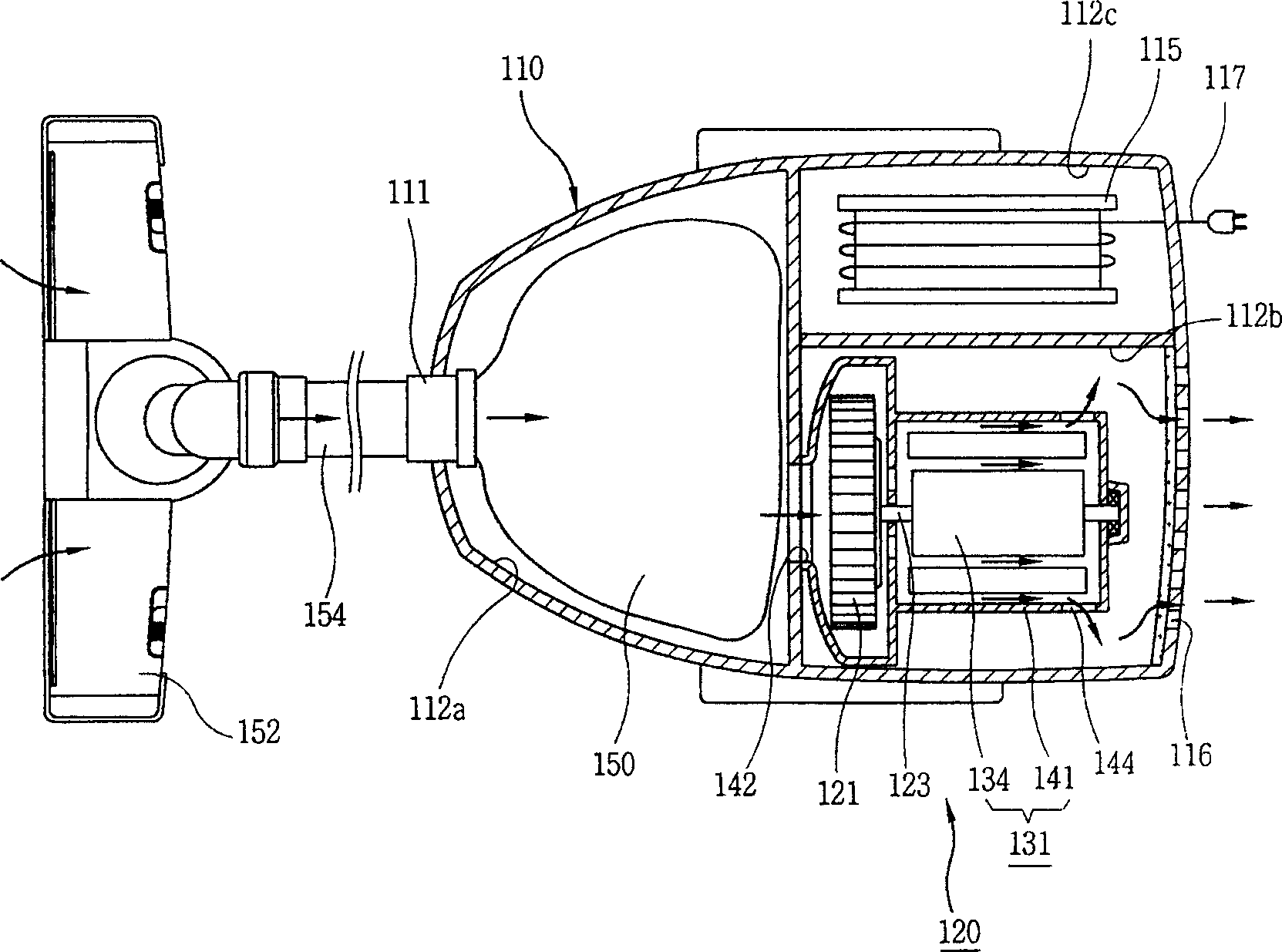
[0004] However, the vacuum cleaner of the prior art has the following disadvantages: since the suction port 142 is along the axial direction of the impeller 121, the exhaust port 144 is on the side of the casing 141 and is perpendicular to the axial direction of the impeller 121, and the air suction The gas sucked into the casing 141 by the port 142 flows along the axial direction to the motor part 131, and then changes the flow direction almost vertically and is discharged through the exhaust port 144, resulting in an increase in the flow resistance of the gas.
In addition, the gas discharged through the exhaust port 144 changes the flow direction and is discharged to the outside of the casing 110 through the discharge port 116 at the rear end of the casing 110, which also has the problem of increasing flow resistance.
Due to the inconsistency between the above-mentioned suction fan 120 and the suction port 142 of the suction fan 120, the exhaust port 144 of the suction fan 120, and the discharge port 116 of the casing 110, the gas flow resistance is increased, and the suction force is relatively reduced, and the reduction of the suction force is not only It affects the dust collection performance, and causes the temperature of the motor part 131 to rise, prompting the motor to be forcibly heated

Method used


Image

  • Vacuum cleaner having suction fan
  • Vacuum cleaner having suction fan
  • Vacuum cleaner having suction fan

Examples


Embodiment Construction

[0014] Below in conjunction with accompanying drawing and specific embodiment the present invention is described in further detail:

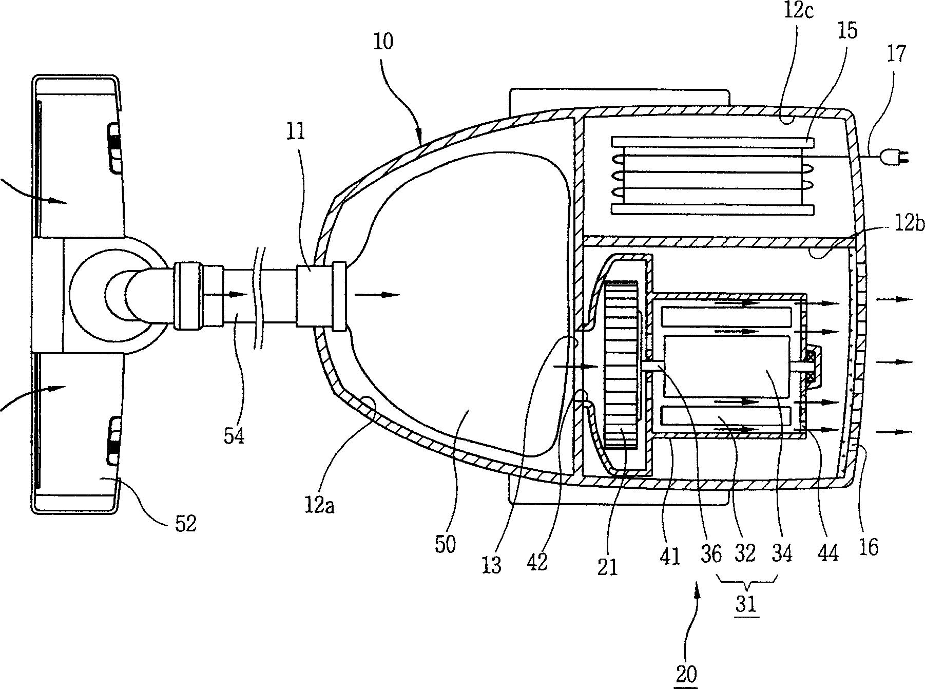
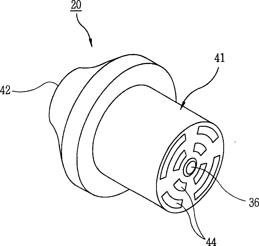
[0015] Such as figure 2 , 3 , 4, the vacuum cleaner of the present invention has the following structure: the interior of the housing 10 forms a storage space, and the rear end forms a discharge port 44; Air port 44, make exhaust port 44 correspond to discharge port 16 along the extension line of the flow direction of gas, suction fan 20 is put into the inside of shell 10, produces suction; The front of 20 is provided with a dust bag 50 that collects foreign matter such as dust in the gas; the connecting pipe 54 is connected to one side of the housing 10; the suction head 52 communicates with one end of the connecting pipe 54 to suck gas and foreign matter from the outside.

[0016] One side of the casing 10 has an interface 11 for connecting the connecting pipe 54; the other side of the interface 11 has a dust bag placement space 12a for put...


PUM


Abstract

A vacuum cleaner with inspiratory fan is disclosed. The vane wheel of insperatory fan is driven by a motor. It features that an air inlet and an air outlet are made up on the casing in such a manner than the air inlet, the air outlet, the vane wheel and the motor are coaxial for increased suction force and the motor is well cooled.

Description

technical field [0001] The invention relates to the field of vacuum cleaners, in particular to vacuum cleaners which increase the suction force by reducing the flow resistance of gas. Background technique [0002] In general, a horizontal section view of a prior art vacuum cleaner is shown as figure 1 As shown, the vacuum cleaner has the following structure: the inside of the casing 110 has a space; the suction fan 120 generating suction is placed inside the casing 110; the dust bag 150 is located in front of the suction fan 120, and the inside of the dust bag 150 collects the dust in the gas And foreign matters; the suction head 152 can suck foreign matter such as dust from the outside; the connecting pipe 154 connects the suction head 152 and the casing 110 . One side of the casing 110 has an interface 111 for connecting the connecting pipe 154; one side of the interface 111 has a dust bag placement space 112a where the dust bag 150 can be placed. There is an air suction...

Claims


Application Information

Patent Timeline
IPC IPC(8): A47L5/22
Inventor 洪尚郁
Owner LG ELECTRONICS (TIANJIN) APPLIANCES CO LTD
Learn More