
Motion device of drum type brake

A technology of drum brakes and brakes, which is applied in the direction of drum brakes, brake types, brake actuators, etc., can solve problems such as deformation, and achieve the effects of reducing prices, preventing interference, and eliminating the worry of damaging brake cables

Inactive Publication Date: 2003-07-09
NISSHINBO IND INC
View PDF0 Cites 6 Cited by
  • Summary
  • Abstract
  • Description
  • Claims
  • Application Information

AI Technical Summary

Problems solved by technology

However, as understood from the above-mentioned arrangement structure of the brake cable 26, the inside of the brake cable 27 until the side connected to the operating device is connected with Image 6 The slack state shown by the double-dot dash line in the figure is bent toward the bottom of the brake drum outside the figure together with the cable return spring 29, elastically deforming

Method used


Image

  • Motion device of drum type brake
  • Motion device of drum type brake
  • Motion device of drum type brake

Examples


Embodiment Construction

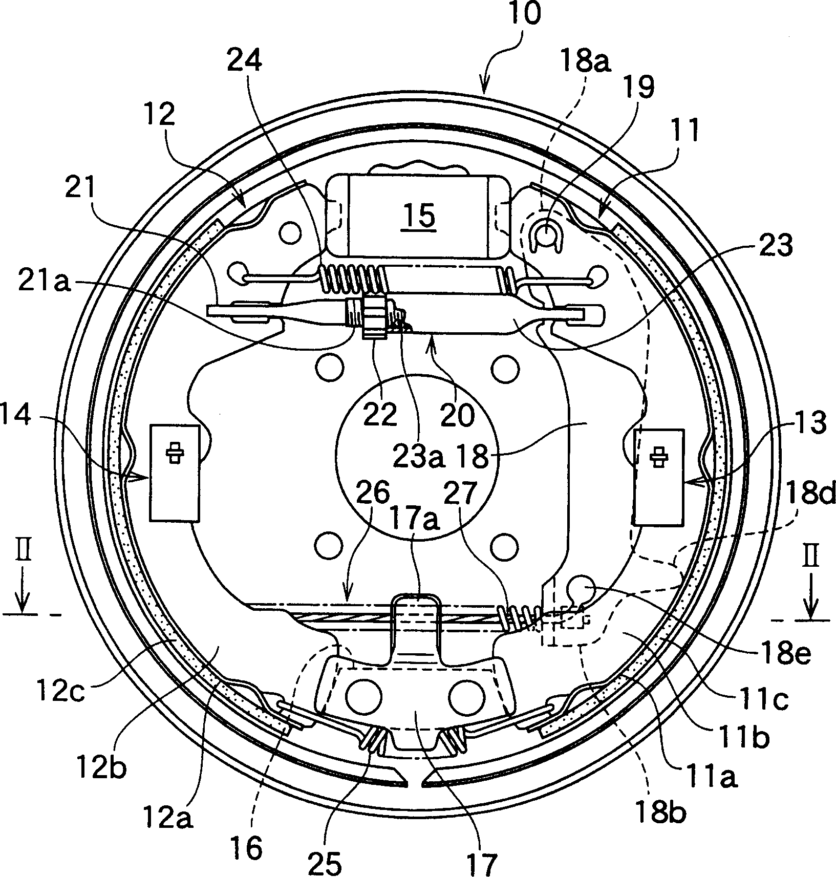
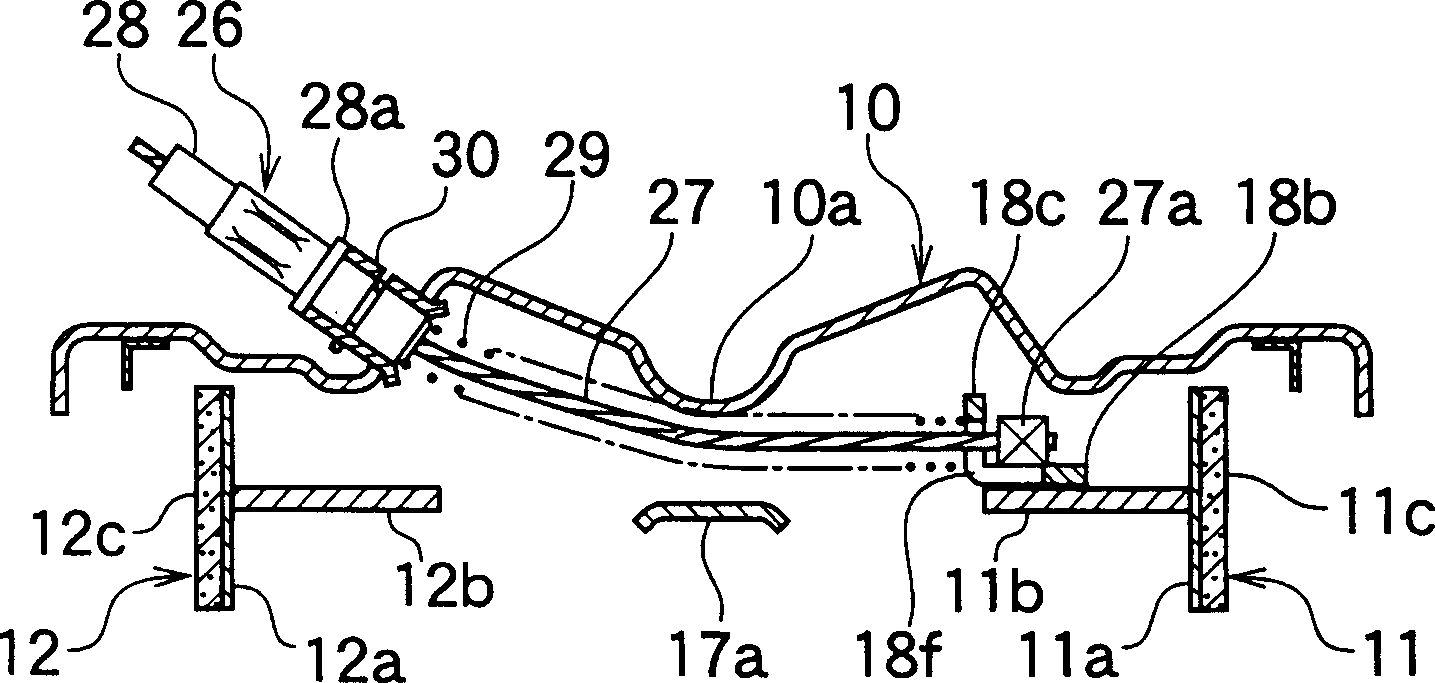
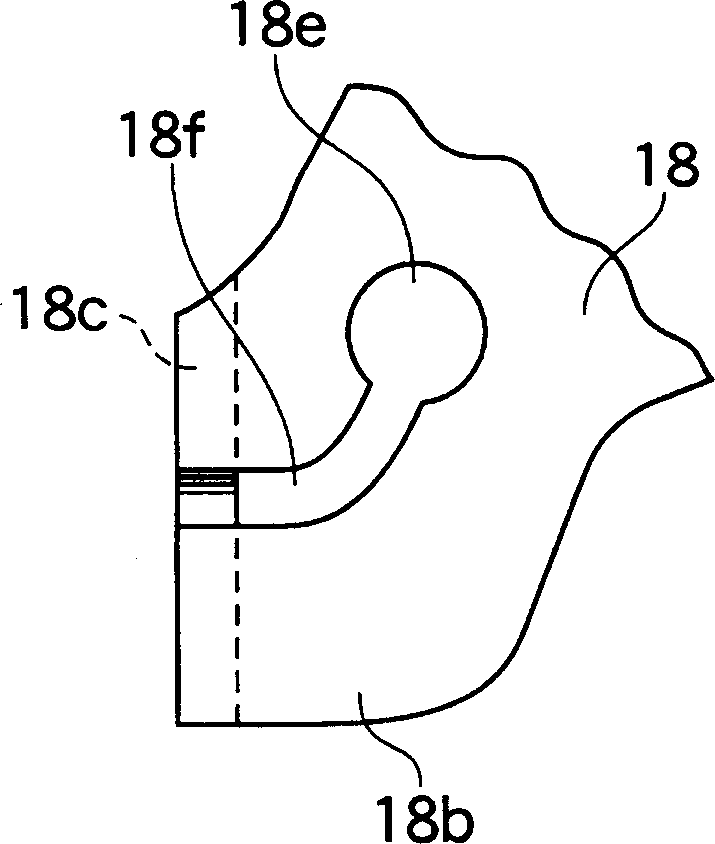
[0038] Next, an example of the operating device of the drum brake of the present invention will be described. In the description, the same reference numerals are attached to the same components and parts as those in the above-mentioned prior art, and their descriptions are omitted, and only the different points will be described here. In addition, since the braking operation is the same as the above-mentioned conventional technology, its description is also omitted here.

[0039] Now refer to the structure of the present invention Figure 1 ~ Figure 3 Be explained. However, the structure of the present embodiment is such that the slit 18f formed on the free end portion 18b of the main body of the brake lever 18 is removed from the figure 1 The upper right side extends toward the lower left side in a substantially circular arc shape, and the through hole 18e through which the cable end 27a passes is located on the inner side of the brake than the inner edge of the shoe web 1...


PUM


Abstract

The invention relates to a drum brake operating device effectively eliminating the possibility of damaging a brake cable with excellent performance in engaging and disengaging the brake cable. A cable end (27a) of an inner cable (27) is hooked and rested on a bending section (18c) directly extending from a free end (18b) of a brake lever (18), a through hole (18e) through which the cable end (27a) passes is formed on the free end (18b) parallel to the shoe web (11b) at an inner side of the brake relative to an inner circumferential edge of a shoe web (11b).

Description

technical field [0001] The present invention relates to an operating device of a drum brake, and more particularly, to a structure for connecting a brake cable as a transmission part for transmitting force from a long distance to a brake lever of an expanded brake shoe. Background technique [0002] The brake cable is used to pull and extend the bending part formed on the inside of the brake at the free end of the brake lever to operate, so that the brake shoe and the brake drum are frictionally fitted. The operating device of the drum brake is known in the past. , For example, as disclosed in Japanese Utility Model Publication No. 18259 / 1986. Now its structure is based on Figure 5 and Image 6 Be explained. In addition, "up, down" and "left, right" used in the description are based on Figure 5 based on. [0003] A pair of brake shoes 11, 12 facing each other form shoe rims 11a, 12a and shoe webs 11b, 12b with a T-shaped cross-section respectively. Liners 11c, 12c. Ea...

Claims


Application Information

Patent Timeline
Patent Type & Authority Applications(China)
IPC IPC(8): F16D65/14F16D65/22
CPCF16D2125/62F16D2121/14F16D65/22F16D51/20
Inventor 池田隆志
Owner NISSHINBO IND INC
Learn More