Cooling fan for microwave oven

A technology for cooling fans, microwave ovens, applied in microwave heating, applications, components of pumping devices for elastic fluids, etc., can solve problems such as increased noise level, large suction noise, etc.

Inactive Publication Date: 2003-07-16
LG ELECTRONICS INC
View PDF0 Cites 0 Cited by
  • Summary
  • Abstract
  • Description
  • Claims
  • Application Information

AI Technical Summary

Problems solved by technology

[0012] However, the existing axial flow fan 20 with the above-mentioned structure has the following disadvantages, that is, when the motor 16 drives this axial flow fan 20 to rotate at a speed of 2856RPM, the volumetric flow rate sucked into the furnace 2 is 1.73CMM, and Under such conditions, the noise reaches 43.1db[A], thus generating considerable suction noise during the rotation of the blade 24
[0013] In addition, in consideration of the fact that, as shown in FIG. 3, each blade 24 has a positive pressure acting surface 24b on which a positive pressure is exerted due to suction, and a negative pressure due to exhaust. The negative pressure acting surface 24c applied thereto, and the blade tip 24a formed between the positive pressure acting surface 24b and the distal end of the negative pressure acting surface 24c have a slightly arcuate cross-section, therefore, when the air acts from the positive pressure When the surface 24b crosses the blade tip 24a and flows to the negative pressure acting surface 24c, the level of noise is further increased due to the rapid static pressure recovery phenomenon

Method used


Image

  • Cooling fan for microwave oven
  • Cooling fan for microwave oven
  • Cooling fan for microwave oven

Examples


Embodiment Construction

[0032] Hereinafter, preferred embodiments of the present invention will be described in detail, an example of which is shown in the accompanying drawings. In all the drawings and descriptions, the same parts use the same reference numerals.

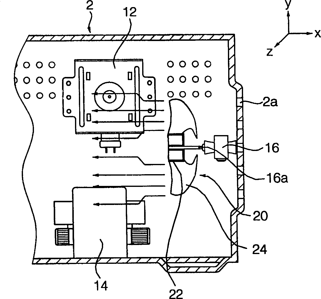
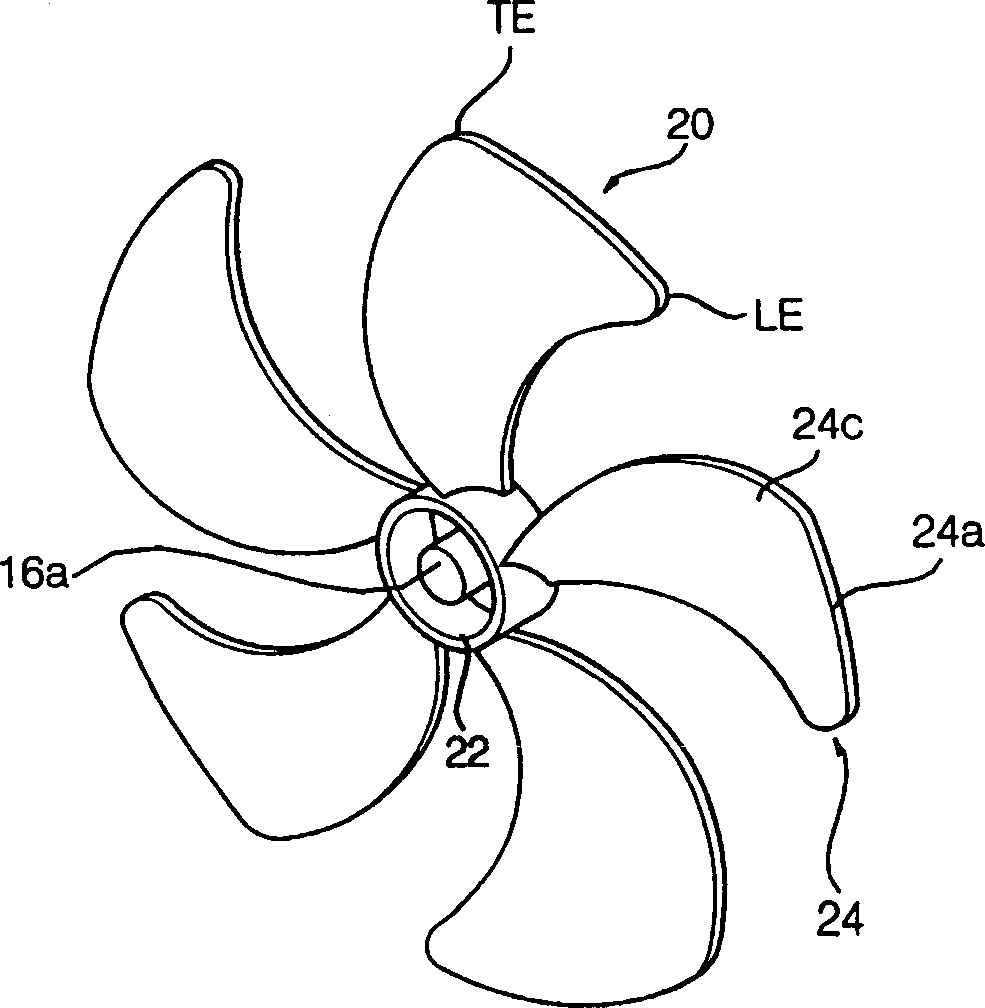
[0033] Figure 4 Is a side sectional view showing a state in which a cooling fan according to the first embodiment of the present invention is installed in the electrical equipment room of a microwave oven; Figure 5 It is a perspective view separately illustrating the cooling fan according to the first embodiment of the present invention.

[0034] Such as Figure 4 As shown, in the electrical equipment room of the microwave oven, a magnetron 62 that emits high-frequency waves into a cooking chamber (not shown in the figure) formed in the furnace 52 is provided above, and a magnetron 62 is provided below to supply high-voltage electricity to the above The high voltage transformer 64 of the magnetron 62. A mixed flow fan 70 is arranged behind...


PUM


Abstract

Disclosed is a cooling fan for a microwave oven, adapted for directing axially sucked airflow to be evenly distributed over a magnetron and a high voltage transformer. The cooling fan comprises a mixed flow fan having a specified hub angle, or an axial flow fan having optimized design parameters such as a ratio of an outer diameter of the fan to a width of a electric device chamber defined in a cabinet, a hub ratio, a sweep angle, a pitch angle, a maximum camber rate, etc.

Description

Technical field [0001] The present invention relates to a cooling fan for cooling a magnetron and a high voltage transformer installed in the electrical equipment room of a microwave oven. More specifically, the present invention relates to such a cooling fan for a microwave oven, which is a kind of cooling fan with a specific hub. Mixed air fan, or an axial fan with preferred design parameters, such as the ratio of the outer diameter of the fan to the width of the electrical device chamber in the furnace, hub ratio, sweep angle, inclination angle, maximum crown, etc. Background technique [0002] Generally, the function of a microwave oven as a household appliance is to use high-frequency electromagnetic waves to increase the molecular motion of the water contained in the food, causing the water molecules to vibrate and generate heat inside the food, so that the food can be cooked in a short time . [0003] The space in the furnace of the microwave oven can be divided into a coo...

Claims


Application Information

Patent Timeline
Patent Type & Authority Applications(China)
IPC IPC(8): F04D29/38H05B6/80
CPCF04D29/384H05B6/642
Inventor 孙尚范
Owner LG ELECTRONICS INC
Why Eureka
Try Eureka