Radio control system and method for projector

A control method and technology of a control system, applied to closed-circuit television systems, parts of TV systems, parts of color TVs, etc., can solve the problem that the projector cannot be connected to the remote control, and the image of the projector cannot be seen on the remote control , unable to send and receive projection data and other issues

Inactive Publication Date: 2003-07-16
SEIKO EPSON CORP
View PDF0 Cites 55 Cited by
  • Summary
  • Abstract
  • Description
  • Claims
  • Application Information

AI Technical Summary

Problems solved by technology

[0008] However, by operating the projector 20 itself or controlling the projector 20 according to an instruction from the notebook personal computer 30, the projector 20 can only be controlled by a person who is near these projectors 20 or the notebook personal computer 30.
In addition, although the projector can be controlled by a remote controller conventionally, since the projector and the remote controller cannot be connected to enable two-way communication, projection data, etc. Image being projected, etc.

Method used


Image

  • Radio control system and method for projector
  • Radio control system and method for projector
  • Radio control system and method for projector

Examples


no. 1 Embodiment

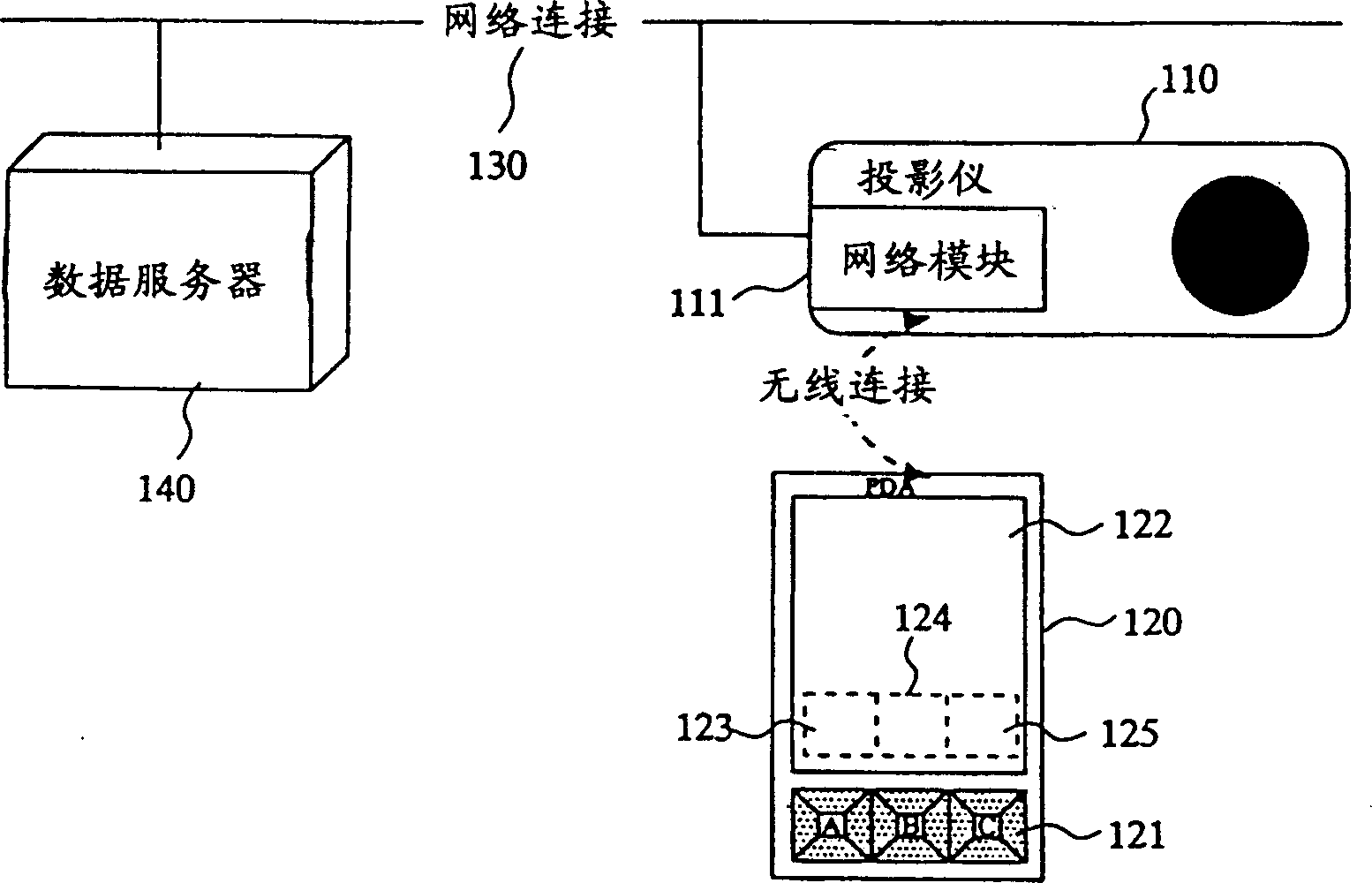
[0055] figure 1 is a configuration diagram of a wireless control system for a projector according to an embodiment of the present invention. This system includes a projector 110 as a projection device having a network module 111 for communicating with other devices, and a portable terminal 120 that is wirelessly connected via the projector and the network module 111 to enable two-way communication (for example, network connection). . In addition, the data server 140 is connected to the projector 110 via the network module 111 and the network line 130 as needed.

[0056] In addition, as the form of the above-mentioned wireless connection, a wireless LAN, Bluetooth (Bluetooth SIG, Inc., a registered trademark of the United States), or the like can be used. In addition, when the communication between the mobile terminal 120 and the projector 110 is established, a connection request may be sent from the mobile terminal 120 to the projector 110 first, and the projector 110 may e...

no. 2 Embodiment

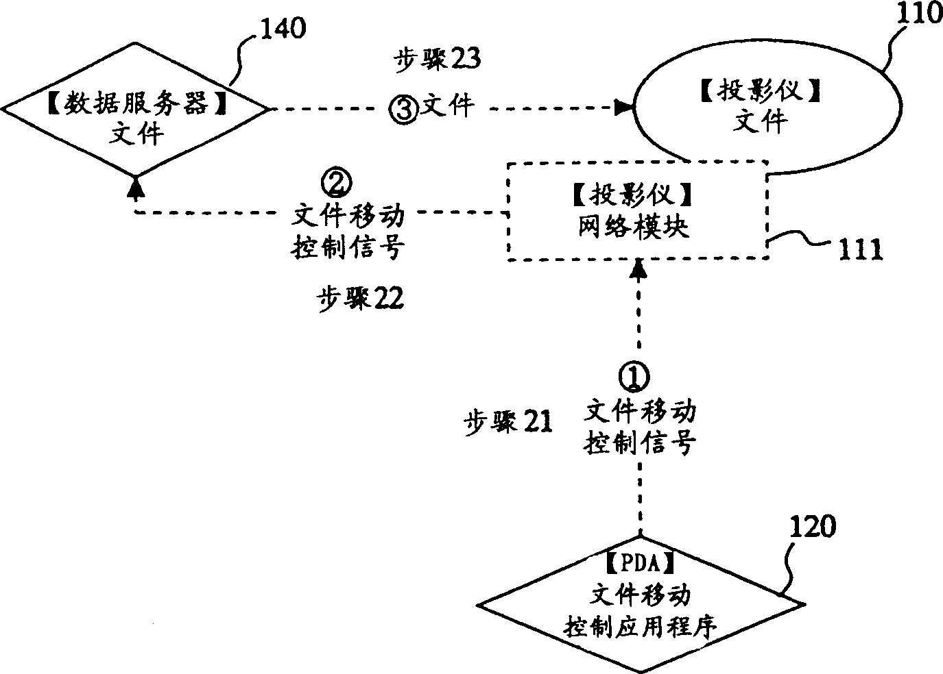
[0069] Image 6 is a diagram showing a wireless control system for a projector according to another embodiment of the present invention. This system includes a projector 110 as a projection device having a network module 111 for communication with other devices, and a portable terminal 120 connected by wireless connection via the projector and the network module 111 so as to enable two-way communication. In addition, as the form of the above-mentioned wireless connection, a wireless local area network or Bluetooth (Bluetooth SIG, Inc., a registered trademark of the United States) can be used. Furthermore, in Image 6 endowed with figure 1 Those with the same label refer to the figure 1 those same or equivalent things.

[0070] exist Image 6 Among them, the projector 110 has a remote control application 112 for enabling a projection operation by remote control of the projector. On the other hand, the portable terminal 120 has a web application control module 126 for re...


PUM


Abstract

A projector and a mobile terminal are connected wirelessly in two-way communication, and thus the projector is controlled by the mobile terminal. Also, projection data is exchanged between the mobile terminal and the projector, or between a data server connected to a network and the projector using a command of the mobile terminal. Furthermore, when a plurality of mobile terminals send projection data simultaneously, a communication enabled state is established with only one mobile terminal by a predetermined procedure, or one projector's projection screen is divided in order to project a plurality of projection data simultaneously.

Description

technical field [0001] The present invention relates to control of a projector using a portable terminal that communicates through a wireless connection. Background technique [0002] Figure 15 It is a configuration diagram showing an example of a conventional projector system connected to a network. exist Figure 15 In the network 10, a projector 20, a notebook personal computer 30, a server 40, and desktop personal computers 51, 52, 53, and 54 are respectively connected. Furthermore, tablets 61 , 62 , 63 , and 64 are directly connected to the projector 20 . [0003] Control information and projection data from the notebook personal computer 30 are sent to the projector 20 via the network 10 , and the data are projected on the projection surface 70 . In addition, the notebook personal computer 30 also sends control information to the server 40 or the desktop personal computers 51, 52, 53, 54 via the network 10, and the projection data stored in the server 40 or the deskt...

Claims


Application Information

Patent Timeline
Patent Type & Authority Applications(China)
IPC IPC(8): H04N5/00H04N5/74H04N7/18
CPCH04N21/42204H04N7/181H04N5/74H04N9/3147H04N21/4316H04N5/44582H04N21/47
Inventor 唐泽彻赤岩升一野沟朋弘
Owner SEIKO EPSON CORP
Why Eureka
Try Eureka