
Device for detecting temp in downhole

A technology of downhole temperature and thermometer, which is used in measurement, wellbore/well components, earth-moving drilling, etc., can solve the problems of inconvenient operation and accurate temperature measurement.

Inactive Publication Date: 2003-07-23
霍明远
View PDF0 Cites 0 Cited by
  • Summary
  • Abstract
  • Description
  • Claims
  • Application Information

AI Technical Summary

Problems solved by technology

[0003] In order to solve the problem that the traditional device for measuring downhole temperature does not move accurately and is not easy to operate, the present invention provides a device for measuring downhole temperature that reflects the accurate temperature of the temperature measuring point

Method used


Image

  • Device for detecting temp in downhole
  • Device for detecting temp in downhole

Examples


Embodiment Construction

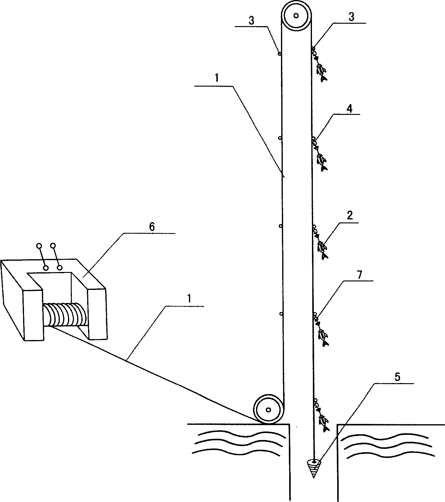
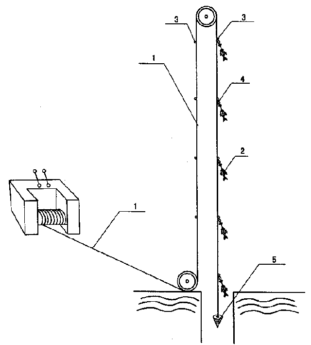
[0009] according to figure 1 As shown, the present invention is mainly composed of a small hoist 6, a steel wire rope or a steel wire rope coated with a polymer material 1, a press-fit movable connection card 4, and a spot thermometer 2. The inside of the notch of the metal loop hook of the press-fit movable connection card 4 is provided with a metal elastic sheet 7, the end of the metal elastic sheet 7 is longer than the notch, the end of the rope 1 is provided with a tapered plumb 5, and a spot thermometer 2 is provided There is a fish-shaped thermometer box that can be opened and closed. One end of the rope 1 is wound in the small hoist 6, and the other end passes through a lower positioning pulley set at the wellhead, and then passes through an upper positioning pulley set on the top of the derrick and then extends into the well. The retention thermometer 2 is provided with a section of thin steel wire sling. The retention thermometer 2 can be fixed to the press-fit movable co...


PUM


Abstract

An equipment for measuring underground temp in well is composed of cable and its winder, and stationary-point thermometers. The part of cable, which is in the well, has the rings at 100 m of intervals for hanging the stationary-point thermometers from them and a conic lead weight at its lower end. Its advantages are easy operation and high correctness.

Description

Technical field [0001] The invention relates to a device for measuring downhole temperature in a drilling crew. Background technique [0002] At present, the drilling crew measures downhole temperature by rope winding equipment, rope rope, test probe and TYSC-3Q electrical method tester. In addition, the measurement process needs to lower the test probe at a constant speed, and then the data obtained through the speed, time and probe will be automatically converted to display the temperature and depth values. However, because it is carried out dynamically, the temperature of the temperature measurement point and the temperature transfer and displacement of the relatively thick test probe have a certain deviation. In addition, the test probe is more than 1 meter in length, which is relatively heavy and easy to operate. Summary of the invention [0003] In order to solve the problems that the traditional downhole temperature measurement device does not move accurately and the oper...

Claims


Application Information

Patent Timeline
Patent Type & Authority Applications(China)
IPC IPC(8): E21B47/07
Inventor 霍明远
Owner 霍明远
Learn More