Method of rolling sheet and rolling machine

A thin plate rolling mill, rolling direction technology, applied in metal rolling stands, metal rolling, metal rolling and other directions, can solve problems such as insufficient mechanical strength

Inactive Publication Date: 2003-07-23
KAWASAKI HEAVY IND LTD +1
View PDF0 Cites 7 Cited by
  • Summary
  • Abstract
  • Description
  • Claims
  • Application Information

AI Technical Summary

Problems solved by technology

However, since one of the work rolls in the reducing mill is thinner, the mecha...

Method used


Image

  • Method of rolling sheet and rolling machine
  • Method of rolling sheet and rolling machine
  • Method of rolling sheet and rolling machine

Examples


Embodiment Construction

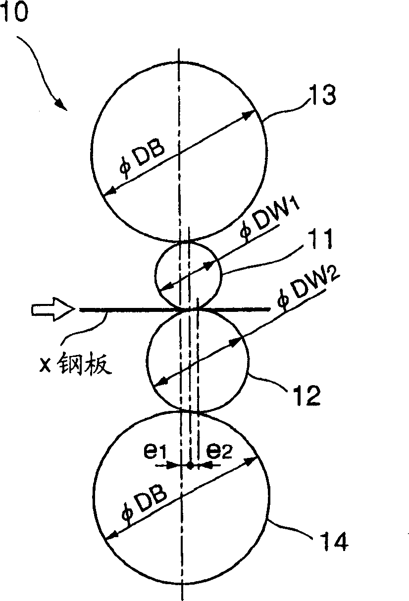
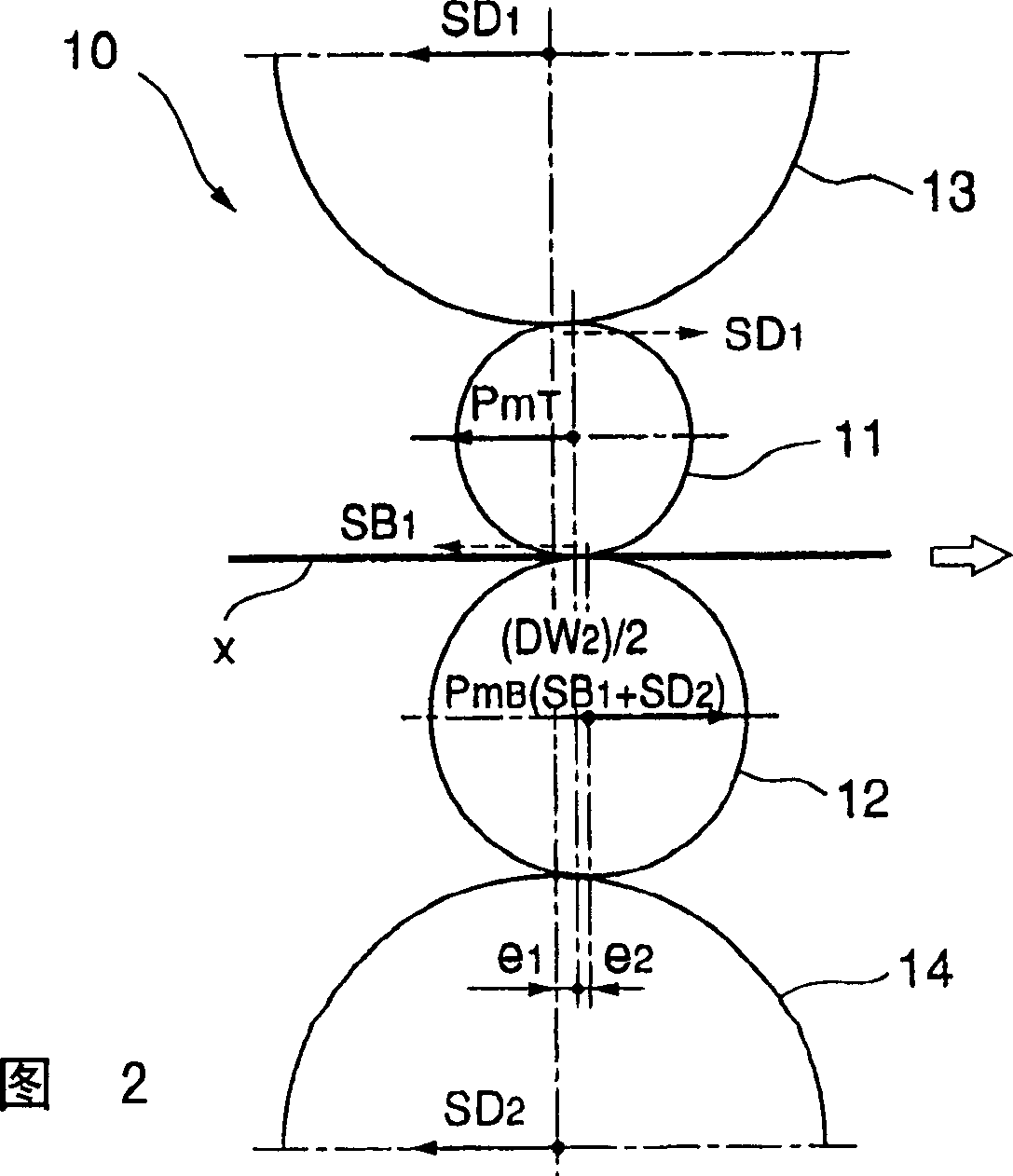
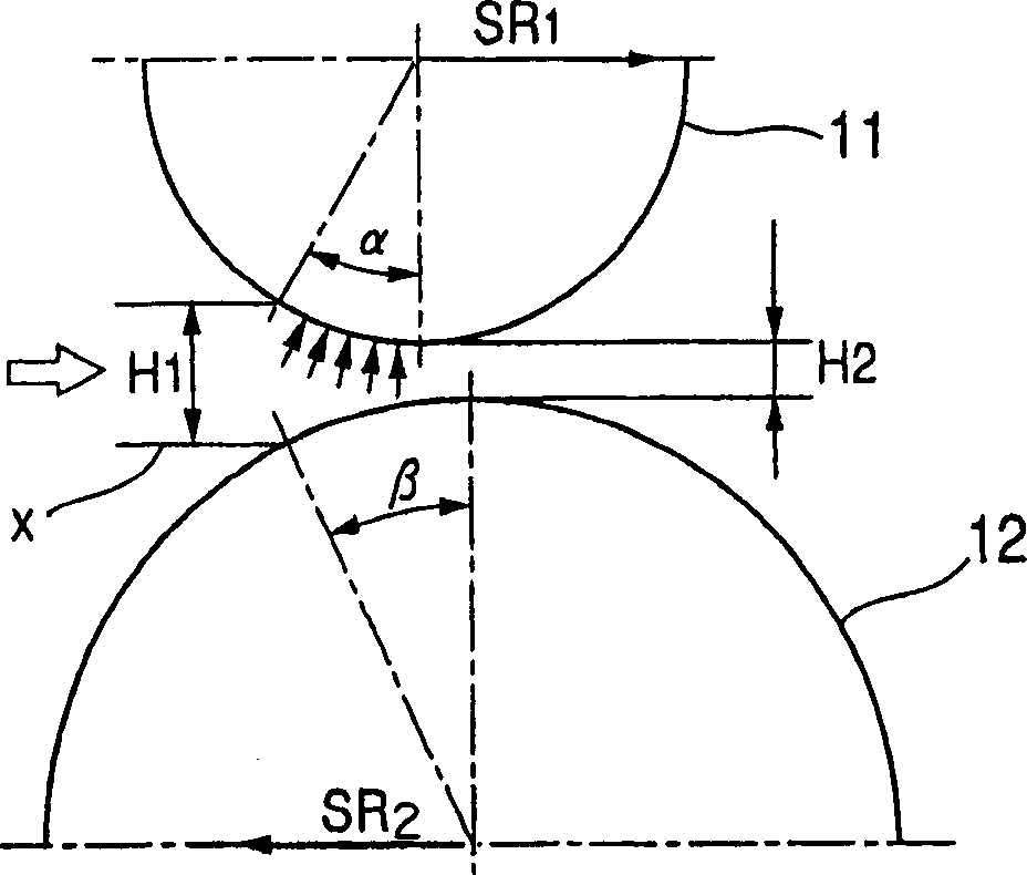
[0043] Figure 1-Figure 7 An embodiment of the invention is shown. figure 1 schematically represented in side view on Figure 7 The basic structure of a rolling mill 10 of one of the rear (downstream side) three-stand rolling mills 1 in the rolling equipment (rolling group) 1 is shown.

[0044] Rolling equipment is equipment for hot rolling thin steel plates such as Figure 7 As shown, it is equipped with a total of six rolling mills 5 and 10 in series. The three-stand rolling mill 5 of the front section (upstream side) is a common four-high rolling mill 5, which consists of a pair of equal-diameter work rolls 6,7 arranged up and down and upper and lower back-up rolls 8,9 supporting the work rolls respectively. The three-stand rolling mill 10 of the rear section is a so-called different diameter rolling mill, and it is provided with a pair of different work rolls 11,12 of diameter between the last back-up roll 13 and the bottom back-up roll 14. Although the upper and lowe...


PUM


Abstract

A method of manufacturing a sheet by disposing a pair of working rolls (11, 12) of different diameters between upper and lower reinforcement rolls (13, 14) and driving only the large diameter work roll (12) of these working rolls so as to roll a plate material (x), comprising the steps of disposing only a small diameter working roll (11) of the pair of working rolls is disposed so that the rotating axis thereof is positioned over a mill center or on the downstream side of the mill center in the rolling direction and disposing the large diameter working roll (12) so that the rotating axis thereof is positioned on the downstream side of the rotating axis of the small diameter working roll (11) in the rolling direction before the plate material is rolled, whereby the dynamic burden of the working rolls can be reduced even when a rolling load is increased due to an increase in rolling width.

Description

technical field [0001] The present invention relates to a rolling mill equipped with a pair of work rolls of different diameters and a method of rolling a thin plate using the rolling mill. Background technique [0002] A conventional rolling mill is a rolling mill in which the diameters of a pair of upper and lower work rolls supported by upper and lower back-up rolls are different and only a thicker work roll, that is, a large-diameter work roll, is driven by a motor, etc., thereby rolling Making thin plates. Compared with a conventional rolling mill equipped with work rolls of the same diameter, this type of rolling mill, called a reducer, can achieve a large reduction at a low rolling load because one of the work rolls is thinner, thus facilitating rolling Sheet steel. Since only a low rolling force is required, edge thinning caused by roll flattening can be suppressed, and a steel sheet with a small thickness error can be advantageously manufactured. [0003] In addi...

Claims


Application Information

Patent Timeline
IPC IPC(8): B21B1/22B21B1/26B21B13/02B21B13/14B21B27/00B21B27/02B21B31/20
CPCB21B1/26B21B2013/025B21B27/00B21B2267/065B21B2031/206
Inventor 高桥昌范足立明夫高冈真司竹士伊知郎仓桥隆郎
Owner KAWASAKI HEAVY IND LTD
Why Eureka
Try Eureka